EE-106 Basic Electrical Technology Oct-Nov 2025 paper solved: Wheatstone bridge, kettle efficiency and maximum power transfer
 Nookesh Karri ·· 48 min read

This post solves the AP SBTET C-23 DEEE first year basic electrical technology question paper of October 2025 (EE-106, October/November 2025 board exam). It answers all 10 Part A questions and all 8 Part B questions. Each question first explains the theory in simple words, then gives the exam answer sized to the marks, with every sum recomputed and every circuit redrawn with the paper’s values. You can open the original question paper PDF next to this page and check each answer.
Basic Electrical Technology question paper October 2025: pattern and syllabus units
The EE-106 paper of October 2025 follows the usual C-23 pattern: 3 hours, 80 marks, Part A with 10 questions of 3 marks (30 marks, all compulsory) and Part B with 8 questions of 10 marks, of which you answer any five (50 marks). The questions map exactly onto the unit blueprint of the C-23 curriculum: 3, 1, 3, 1 and 2 short questions, and 1, 2, 2, 1 and 2 essay questions from Units 1 to 5.
Part A instructions as printed on the paper (PART—A, 3×10=30):
Instructions : (1) Answer all questions.
(2) Each question carries three marks.
(3) Answers should be brief and straight to the point and shall not exceed five simple sentences.
Part B instructions as printed on the paper (PART—B, 10×5=50):
Instructions : (1) Answer any five questions.
(2) Each question carries ten marks.
(3) Answers should be comprehensive and the criteria for valuation is the content but not the length of the answer.
| Q no | Topic | Syllabus unit | Marks |
|---|---|---|---|
| 1 | Ohm’s law | Unit 1 Basic Principles of Electricity | 3 |
| 2 | Current from charge and time | Unit 1 | 3 |
| 3 | Temperature coefficient of resistance | Unit 1 | 3 |
| 4 | Active and passive circuits | Unit 2 Resistive Circuits | 3 |
| 5 | Electrical power and its unit | Unit 3 Work, Power, Energy and Heating | 3 |
| 6 | Joule’s law of heating | Unit 3 | 3 |
| 7 | Energy used by a heater | Unit 3 | 3 |
| 8 | Ideal current source | Unit 4 Conversion Techniques | 3 |
| 9 | Superposition theorem | Unit 5 Network Theorems | 3 |
| 10 | Need for network theorems | Unit 5 | 3 |
| 11 | Rₜ = R₀(1 + α₀t), carbon block resistance | Unit 1 | 10 |
| 12 | Current division rule | Unit 2 | 10 |
| 13 | Wheatstone bridge by Kirchhoff’s laws | Unit 2 | 10 |
| 14 | Monthly electricity bill | Unit 3 | 10 |
| 15 | Electric kettle efficiency | Unit 3 | 10 |
| 16 | Delta to star transformation | Unit 4 | 10 |
| 17 | Thevenin’s theorem | Unit 5 | 10 |
| 18 | Maximum power transfer theorem | Unit 5 | 10 |
My advice: in Part B, pick Q12, Q14, Q17, Q18 and Q11. Each is a short sum with one method, so you can finish it in about 20 minutes and still check it. Leave Q13 for last; three simultaneous equations eat time and one sign slip spoils the answer. You can see every EE-106 session together on the Basic Electrical Technology subject page.
Q1. State Ohm’s law. (3 marks)
Understand it first
- Voltage (V) is the electrical push that drives charges. It is measured in volts.
- Current (I) is the flow of charge. It is measured in amperes.
- Resistance (R) is how much a material opposes the flow of current. It is measured in ohms (Ω).
- Ohm’s law links these three. It says the push and the flow rise together.
Think of water in a pipe. Double the pressure, and the flow doubles. In a wire, double the voltage and the current doubles. That is what “directly proportional” means.
The temperature must stay constant because heat changes the resistance of a metal (Q3). If R changes, the ratio V / I changes, and the straight-line rule breaks.
If you plot V against I for such a conductor, you get a straight line through the origin. Its slope is R. Example: 6 V across a 3 Ω resistor gives I = 6 / 3 = 2 A. Make it 12 V, and I = 4 A.
Exam answer (3 marks)
- Statement: at constant temperature, the current flowing through a conductor is directly proportional to the potential difference across its ends: I ∝ V.
- Formula: V / I = constant = R, so V = I × R, where R is the resistance of the conductor.
- Units and condition: V in volts, I in amperes, R in ohms (Ω). The law holds only when temperature and other physical conditions stay constant.
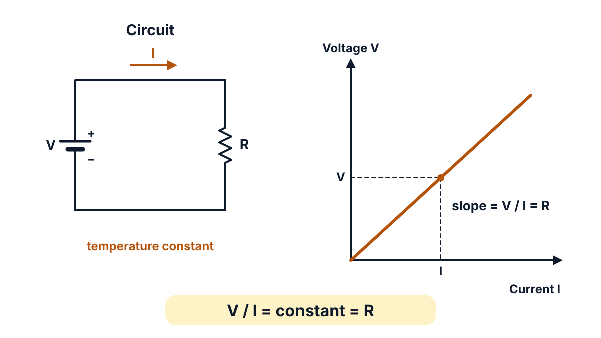
Figure Q1: at constant temperature the V-I graph of a conductor is a straight line through the origin; its slope V / I is the resistance R.
Key points to write: I ∝ V at constant temperature; V = IR; units volt, ampere, ohm.
Q2. A charge equal to 5.6 Coulombs is crossing over a point in a circuit in 2.8 sec. Find the current flowing in the circuit. (3 marks)
Question (as printed): 2. A charge equal to 5.6 Coulombs is crossing over a point in a circuit in 2.8 sec. Find the current flowing in the circuit. 3
Understand it first
- Charge (Q) is the basic quantity of electricity. Electrons carry it. It is measured in coulombs (C).
- Current is the rate of flow of charge. It tells you how many coulombs pass a point every second.
- So current = charge ÷ time, or I = Q / t.
- One ampere means one coulomb passing a point every second.
Think of counting people walking through a gate. If 56 people pass in 28 seconds, then 2 people pass each second. Current counts coulombs in the same way.
Here 5.6 C passes in 2.8 s. So each second, 5.6 / 2.8 = 2 C pass. That is a current of 2 A.
Keep the units in coulombs and seconds; if time were given in minutes, you would change it to seconds first.
Exam answer (3 marks)
- Given and formula: Q = 5.6 C, t = 2.8 s. Current I = Q / t.
- Substitution: I = 5.6 / 2.8.
- Result: I = 2 A.
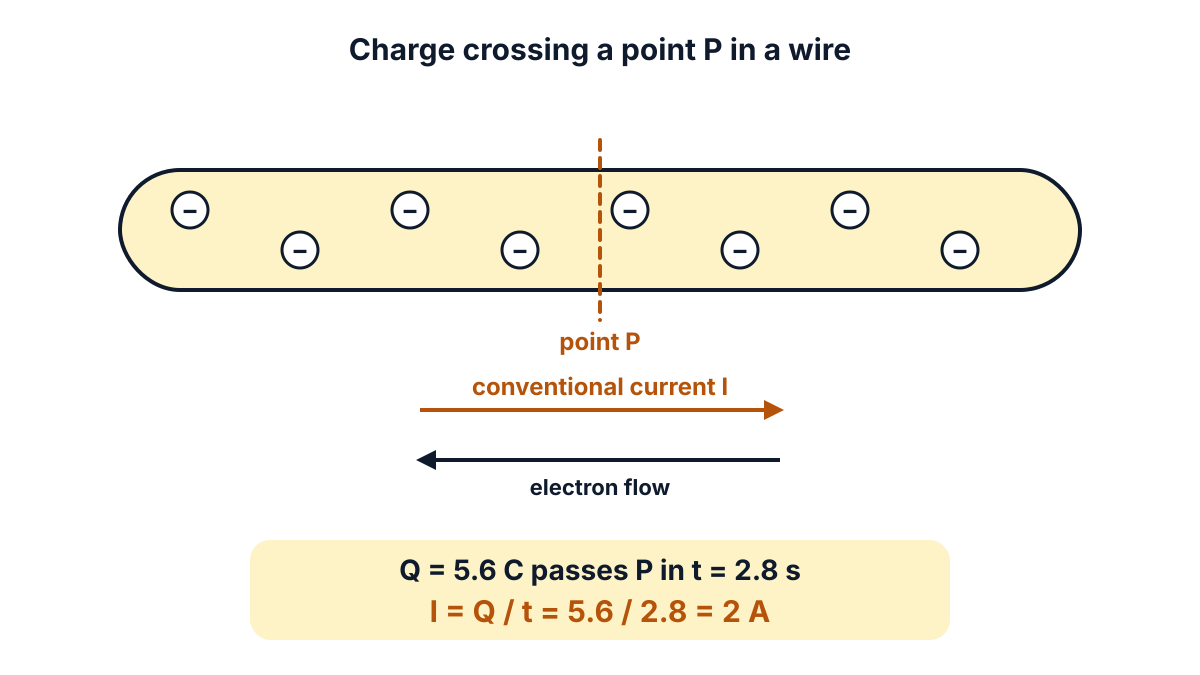
Figure Q2: 5.6 C crosses point P in 2.8 s, so 2 C cross every second, a current of 2 A; conventional current is opposite to the electron flow.
Answer: I = 2 A.
Q3. Define temperature coefficient of resistance and state its SI units. (3 marks)
Question (as printed): 3. Define temperature coefficient of resistance and state its SI units. 2+1
Understand it first
- When a metal gets hotter, its atoms vibrate more strongly.
- Moving electrons bump into these vibrating atoms more often.
- More collisions mean more opposition. So the resistance of a metal rises with temperature.
- In carbon, semiconductors, insulators and electrolytes, heat frees more charge carriers. So their resistance falls with temperature.
Think of walking through a corridor. If the people in it start running about, it is harder to get through. That is a hot metal.
The temperature coefficient of resistance (α, alpha) measures how fast resistance changes with temperature. It answers one question: “For every 1 Ω, how many ohms are added for each 1 °C rise?”
The symbol α₀ means the coefficient is worked out from the resistance at 0 °C (R₀). Q11 builds the full formula from this idea.
Units: α is “ohm per ohm per degree”. The ohms cancel. So the unit is simply per °C. A change of 1 °C is the same size as a change of 1 K, so the SI unit is per kelvin (K⁻¹).
Exam answer (3 marks)
This question has two parts: the definition for 2 marks and the SI unit for 1 mark.
Definition (2 marks).
- Meaning: the temperature coefficient of resistance of a material is the change in resistance per ohm of original resistance per °C change in temperature.
- Formula: α₀ = (Rₜ − R₀) / (R₀ × t), where R₀ is the resistance at 0 °C and Rₜ the resistance at t °C. It is positive for metals and negative for carbon and insulators.
SI unit (1 mark).
- Unit: per kelvin (K⁻¹), which in practice is written per °C (/°C).
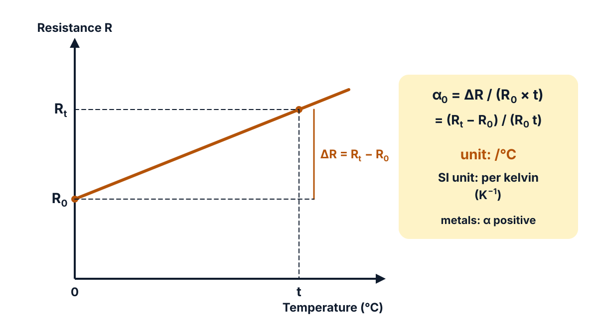
Figure Q3: the rise in resistance ΔR = Rₜ − R₀ divided by R₀ and by the temperature rise t gives α₀.
Key points to write: change in resistance per ohm per °C; α₀ = (Rₜ − R₀)/(R₀t); SI unit K⁻¹ (/°C).
Q4. Write any three differences between active and passive circuits. (3 marks)
Understand it first
- A circuit element is any part of a circuit, such as a battery, a resistor or a coil.
- An active element can supply energy to the circuit. Batteries, generators and other voltage or current sources are active.
- A passive element cannot supply energy. It only uses it (a resistor turns it into heat) or stores it (an inductor in its magnetic field, a capacitor in its electric field).
- An active circuit contains at least one source. A passive circuit has only passive elements and no source.
Think of a water system. The pump is active; it pushes water round. Pipes, taps and tanks are passive; they only carry, slow down or store the water. Without the pump, nothing flows.
How to spot the difference in a diagram: look for a battery or source symbol. If there is one, current flows by itself. If there is none, the network just sits there until you connect a source to it.
Exam answer (3 marks)
| Point | Active circuit | Passive circuit |
|---|---|---|
| Source | Contains one or more sources of EMF or current | Contains no source of energy |
| Energy | Delivers (supplies) energy to the circuit | Only receives energy; uses or stores it |
| Elements and current | Has sources with R, L, C; current flows on its own | Has only R, L, C; no current flows unless a source is connected |
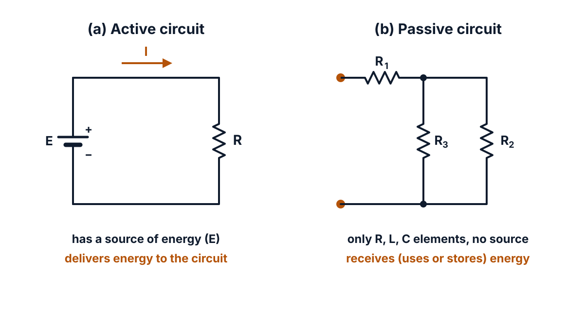
Figure Q4: (a) an active circuit has a source E that drives current; (b) a passive circuit has only resistors and no source.
Key points to write: active = has a source, supplies energy; passive = no source, only uses or stores energy.
Q5. Define electrical power and mention its SI units. (3 marks)
Question (as printed): 5. Define electrical power and mention its SI units. 2+1
Understand it first
- Work or energy is measured in joules (J).
- Power is how fast work is done. It is work ÷ time.
- Two people carry the same bag up the stairs. The faster one has more power, even though both do the same work.
- In a circuit, each coulomb gets V joules from the source. I coulombs flow every second. So the energy per second is V × I. That is why P = V × I.
Put V = IR into P = VI and you get P = I²R. Put I = V/R and you get P = V²/R. All three give the same answer; choose the one that uses the values you know.
Do not mix up power and energy. Power is a rate, in watts. Energy is the total, power × time. A 100 W bulb uses 100 J every second.
Exam answer (3 marks)
This question has two parts: the definition for 2 marks and the SI unit for 1 mark.
Definition (2 marks).
- Meaning: electrical power is the rate at which electrical work is done in a circuit, that is, the rate at which electrical energy is converted into another form such as heat, light or motion.
- Formula: P = W / t = V × I = I²R = V²/R.
SI unit (1 mark).
- Unit: the watt (W); 1 W = 1 joule per second = 1 volt × 1 ampere. Larger units: 1 kW = 1000 W.
Key points to write: rate of doing electrical work; P = VI = I²R = V²/R; watt = J/s.
Q6. State Joule’s law of electrical heating. (3 marks)
Understand it first
- Current is a flow of electrons through a conductor.
- On the way, electrons keep hitting the atoms of the conductor.
- Each hit hands some energy to the atom, which vibrates more.
- Faster vibration means a hotter conductor. So electrical energy turns into heat.
This is like rubbing your hands together; the friction turns your effort into warmth.
Why each factor matters:
- Resistance R: more opposition means more collisions, so more heat.
- Time t: the longer current flows, the more heat builds up.
- Current squared, I²: double the current and the heat becomes four times, because there are twice as many electrons and each one is pushed twice as hard.
Example: 2 A through 10 Ω for 5 s gives H = 2² × 10 × 5 = 200 J. With 4 A, H = 800 J, four times as much.
Heat can also be given in calories. Divide joules by J, the mechanical equivalent of heat (4.186 J per calorie), to get calories.
Exam answer (3 marks)
Joule’s law states that the heat produced in a conductor when current flows through it is directly proportional to:
- the square of the current through it (I²),
- the resistance of the conductor (R), and
- the time for which the current flows (t).
So H = I²Rt joules, or H = I²Rt / J calories, where J = 4.186 J per calorie. The heat chapter of an open physics text gives this value as 1.00 kcal = 4186 J.
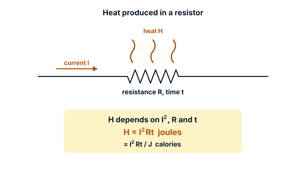
Figure Q6: current I flowing through resistance R for time t produces heat H = I²Rt.
Key points to write: H ∝ I², R and t; H = I²Rt J = I²Rt/4.186 cal.
Q7. An electric heater draws a current of 12 A from a supply of 230 V. If the load is connected for 10 hours, find the energy consumed in kWH. (3 marks)
Question (as printed): 7. An electric heater draws a current of 12 A from a supply of 230 V. If the load is connected for 10 hours, find the energy consumed in kWH. 3
Understand it first
- Power is the rate of using energy: P = V × I, in watts.
- Energy is power × time. If power is in kilowatts and time in hours, energy comes out in kilowatt-hours (kWh).
- 1 kWh is the unit on your electricity bill. It is the energy used by a 1000 W load in 1 hour.
Plan: first find the power in watts, change it to kilowatts (divide by 1000), then multiply by the hours.
Check: a heater is a big load, a few kilowatts. Our 2.76 kW fits. Running it 10 hours uses 27.6 units, which is why heaters push up bills. The paper writes the unit as “kWH”; the standard symbol is kWh.
Exam answer (3 marks)
- Given and power: V = 230 V, I = 12 A, t = 10 h. P = V × I = 230 × 12 = 2760 W = 2.76 kW.
- Energy formula: E = P × t (kW × h).
- Result: E = 2.76 × 10 = 27.6 kWh (27.6 units).
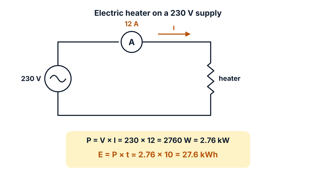
Figure Q7: the heater takes 12 A from 230 V, so it uses 2.76 kW and 27.6 kWh in 10 hours.
Answer: energy consumed = 27.6 kWh.
Q8. Define ideal current source and draw its characteristics. (3 marks)
Question (as printed): 8. Define ideal current source and draw its characteristics. 2+1
Understand it first
- A source supplies electrical energy to a circuit.
- A current source tries to keep the current fixed. (A voltage source tries to keep the voltage fixed.)
- The load is the device that the source feeds, such as a resistor RL.
- “Ideal” means perfect, with no loss inside.
Every real current source has an internal resistance in parallel with it. Some current leaks through this resistance instead of reaching the load. If the internal resistance is infinite, nothing leaks. The load then gets the full current, whatever its value. That is an ideal current source.
Think of a pump that always sends the same litres per second. If the pipe after it gets narrower, the pump just builds more pressure. In the same way, the terminal voltage of an ideal current source changes with the load, but its current never changes.
A characteristic is a graph of current against terminal voltage. For the ideal source it is a flat horizontal line. For a practical source it droops a little as the voltage rises, because more current leaks through the internal resistance.
Exam answer (3 marks)
This question has two parts: the definition for 2 marks and the characteristic for 1 mark.
Definition (2 marks).
- Meaning: an ideal current source is a source that delivers a constant current to any load connected across it, whatever the terminal voltage.
- Internal resistance: its internal resistance, connected in parallel with it, is infinite, so no current is lost inside the source. It is drawn as a circle with an arrow showing the direction of current.
Characteristic (1 mark).
- Graph: current I against terminal voltage V is a horizontal straight line (I constant for all V); a practical source gives a slightly falling line.
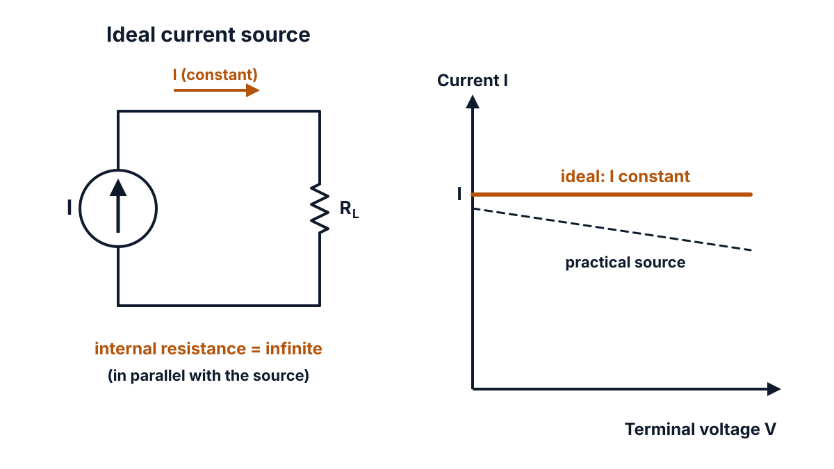
Figure Q8: ideal current source feeding RL, and its characteristic: a flat line for the ideal source and a slightly falling line for a practical one.
Key points to write: constant current for any load; internal (parallel) resistance infinite; flat I-V characteristic.
Q9. State superposition theorem. (3 marks)
Understand it first
- Some circuits have two or more sources. Solving them in one go needs many equations.
- “Superposition” means placing one thing on top of another. We find the effect of each source alone, then add the effects.
- Think of two people pushing a cart. You can work out the push of each person alone. Together, the effect is the sum.
How to “remove” a source while you study the other one:
- An ideal voltage source is replaced by a short circuit (a plain wire), because its internal resistance is zero.
- An ideal current source is replaced by an open circuit (a break), because its internal resistance is infinite.
- If a source has internal resistance, that resistance stays in the circuit.
The theorem works only for linear circuits, where every resistor obeys Ohm’s law. It works for currents and voltages, but not directly for power, because power depends on I² and squares do not add.
Exam answer (3 marks)
- Statement: in a linear, bilateral network containing more than one source, the current through (or voltage across) any element is the algebraic sum of the currents (or voltages) produced by each source acting alone.
- Other sources: while one source acts, every other source is replaced by its internal resistance: ideal voltage sources are short-circuited and ideal current sources are open-circuited.
- Result: I = I′ + I″ + …, adding part currents that flow in the same direction and subtracting those that flow in opposite directions.
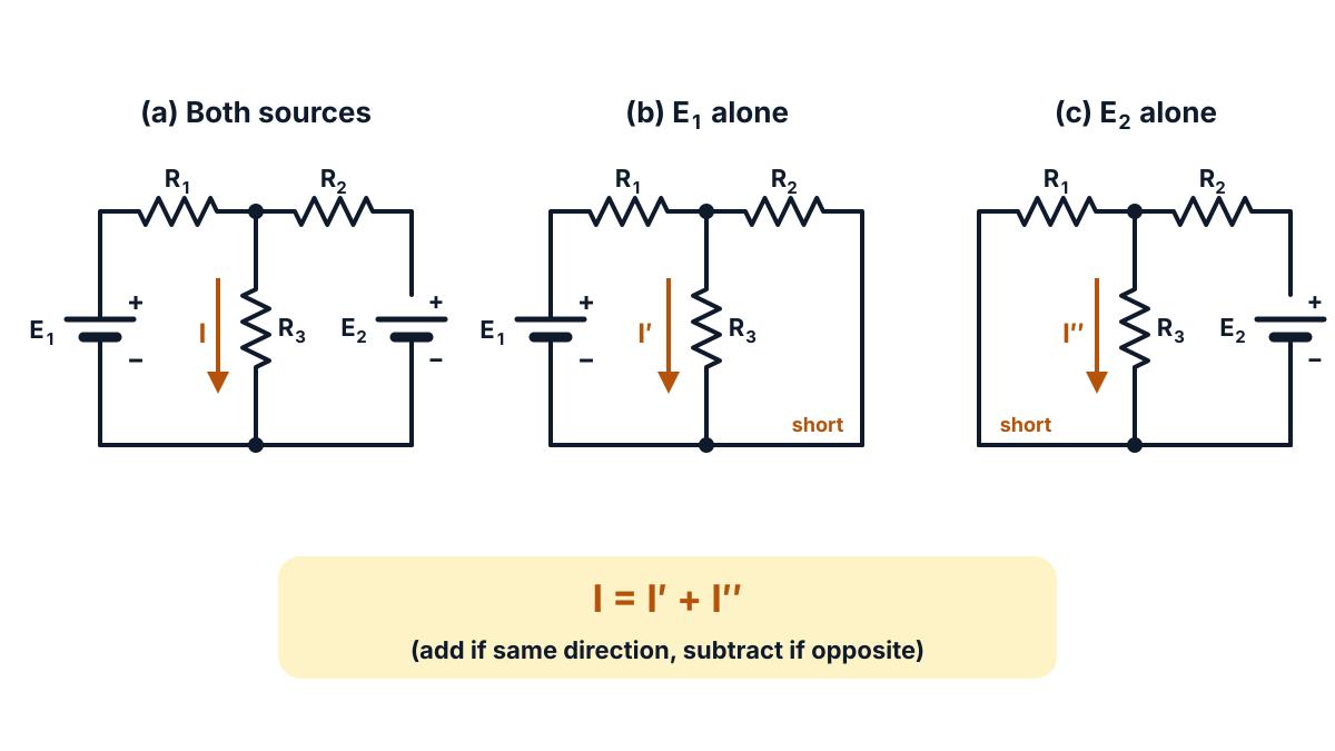
Figure Q9: the current I in R₃ with both sources (a) equals I′ with E₁ alone (b) plus I″ with E₂ alone (c).
Key points to write: linear network, many sources; one source at a time, others replaced by internal resistance; algebraic sum.
Q10. What is the need of network theorems? (3 marks)
Understand it first
- Kirchhoff’s laws can solve any circuit. But each loop gives one equation.
- A large circuit gives many equations. Solving them together takes long and invites mistakes. Q13 of this paper shows how heavy even one bridge can be.
- A network theorem is a proven shortcut. It turns a hard circuit into a simple one that gives the same answer for the part you care about.
Think of finding one friend’s house. You could study the whole city map, or just ask for the road to that house. Theorems give you only the answer you need.
Each theorem of Unit 5 has a job:
- Superposition (Q9): circuits with several sources, taken one at a time.
- Thevenin’s and Norton’s theorems (Q17): the current in one branch, especially when the load keeps changing.
- Maximum power transfer (Q18): which load takes the most power.
Exam answer (3 marks)
Network theorems are needed because large networks with many sources and loops are tedious to solve by Kirchhoff’s laws alone.
- Less work: Kirchhoff’s laws give many simultaneous equations for a large network; a theorem reduces the network to a simple equivalent and cuts the calculation.
- One branch and changing loads: Thevenin’s and Norton’s theorems give the current in one branch directly, and a new load value needs only one more line instead of a full solution.
- Special problems: superposition handles several sources one at a time, and the maximum power transfer theorem finds the load that takes the most power.
Key points to write: simplify analysis, single-branch current, changing loads, multiple sources, maximum power.
Q11. (a) Derive the expression for resistance at any temperature, i.e. Rₜ = R₀ (1 + α₀t) (10 marks)
Question (as printed): 11. (a) Derive the expression for resistance at any temperature, i.e. Rₜ = R₀ (1 + α₀t)
(b) A rectangular carbon block has dimensions 1cm×1cm×50cm. If the resistivity of carbon is 3.5×10⁻⁵ Ω-m, find the resistance between (i) opposite ends (ii) opposite rectangular faces. 4+6
Understand it first
Part (a) builds on Q3. Let a metal wire have resistance R₀ at 0 °C. Heat it to t °C. Its resistance becomes Rₜ.
- Temperature rise: heat it twice as much and the rise in resistance doubles. So the rise ∝ t (“∝” means “is proportional to”).
- Starting resistance: a wire with twice the resistance has twice as many “ohms” to grow. So the rise ∝ R₀.
- Material: copper changes differently from nichrome.
Join points 1 and 2: Rₜ − R₀ ∝ R₀ t. To turn “∝” into “=”, multiply by a constant for the material. That constant is α₀. The rest is simple algebra.
On a graph of R against t, a metal gives a straight line over the normal working range. The line cuts the R-axis at R₀. Its slope is R₀α₀. Extended backwards, it would reach zero resistance at t = −1/α₀, which is called the inferred zero resistance temperature.
Part (b) uses resistivity (ρ, rho). Resistivity is the resistance of a cube of the material with 1 m sides, measured between opposite faces. It is fixed for a material. From it, R = ρ l / A, where l is the length the current travels and A is the area it flows through.
The trick in part (b) is to see which faces the current enters and leaves.
- Between opposite ends: current runs the long way. l = 50 cm, A = 1 cm × 1 cm, a small square. Long path, narrow area: larger R.
- Between opposite rectangular faces: current runs the short way, across 1 cm. A = 1 cm × 50 cm, a big face. Short path, wide area: tiny R.
Always change cm to m before you substitute, because ρ is in ohm-metre.
Exam answer (10 marks)
This question has two parts: (a) for 4 marks and (b) for 6 marks.
(a) Resistance at any temperature (4 marks).
- Experimental facts: let R₀ be the resistance at 0 °C and Rₜ at t °C. The increase in resistance (Rₜ − R₀) is directly proportional to the original resistance R₀, directly proportional to the temperature rise t, and depends on the material.
- Proportion to equation: so Rₜ − R₀ ∝ R₀ t, or Rₜ − R₀ = α₀ R₀ t, where the constant α₀ is the temperature coefficient of resistance at 0 °C.
- Result: Rₜ = R₀ + R₀ α₀ t, so Rₜ = R₀ (1 + α₀t).
- Graph and meaning of α₀: the R-t graph is a straight line with intercept R₀ and slope (Rₜ − R₀)/t = R₀α₀; so α₀ = (Rₜ − R₀)/(R₀t), the change in resistance per ohm per °C at 0 °C.
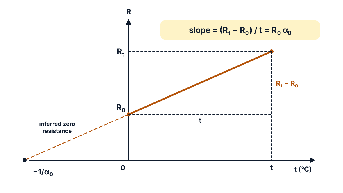
Figure Q11 (a): the R-t line starts at R₀; over a rise of t °C the resistance rises by Rₜ − R₀, so the slope is R₀α₀.
(b) Resistance of the carbon block (6 marks).
- Given and units: ρ = 3.5 × 10⁻⁵ Ω-m; 1 cm = 0.01 m and 50 cm = 0.5 m. Formula: R = ρ l / A.
- (i) Opposite ends, length and area: l = 0.5 m, A = 0.01 × 0.01 = 1 × 10⁻⁴ m².
- (i) Substitution: R = 3.5 × 10⁻⁵ × 0.5 / (1 × 10⁻⁴).
- (i) Result: R = 0.175 Ω.
- (ii) Opposite rectangular faces, length and area: l = 0.01 m, A = 0.01 × 0.5 = 0.005 m² (5 × 10⁻³ m²); R = 3.5 × 10⁻⁵ × 0.01 / 0.005.
- (ii) Result: R = 7 × 10⁻⁵ Ω (0.00007 Ω), which is 2500 times smaller than in case (i).
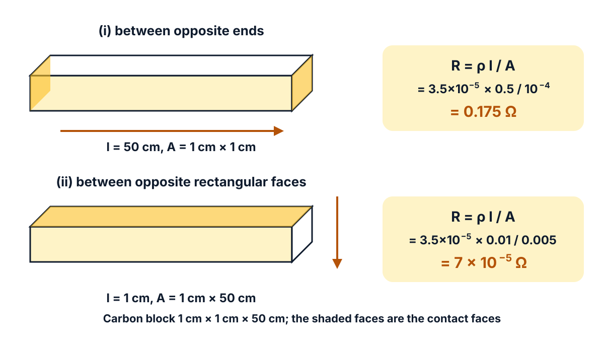
Figure Q11 (b): the same block measured two ways; the long, narrow path gives 0.175 Ω and the short, wide path gives 7 × 10⁻⁵ Ω.
Answer: (a) Rₜ = R₀(1 + α₀t); (b) (i) 0.175 Ω between opposite ends, (ii) 7 × 10⁻⁵ Ω between opposite rectangular faces.
Exam tip: in (ii) the length is the 1 cm thickness, not 50 cm. Mark the two contact faces on your sketch first, then read l and A from it.
Q12. Find the currents flowing through 4 Ω and 6 Ω resistances by using current division rule in the circuit shown below : (10 marks)
Question (as printed): 12. Find the currents flowing through 4 Ω and 6 Ω resistances by using current division rule in the circuit shown below : 10
(Circuit printed on the paper: a 20 V source with current I, a 2 Ω resistor in series, then 4 Ω and 6 Ω in parallel; redrawn in the answer below.)
Understand it first
- Series means one after another, with one path. The same current flows through each part.
- Parallel means side by side, between the same two points. Each branch gets the same voltage, and the current splits.
- Here the 2 Ω is in series with the source. The 4 Ω and 6 Ω are in parallel with each other.
The current division rule tells you how a current splits between two parallel resistors:
- Current in one branch = total current × (the other resistance) ÷ (sum of both).
- Why the “other” resistance? More current takes the easier path. The smaller resistor gets the bigger share.
Think of cars at a fork in the road. A wide road (low resistance) takes more cars than a narrow lane.
Plan: first combine 4 Ω and 6 Ω into one equivalent resistance. Add the 2 Ω. Use Ohm’s law for the total current I. Then split I with the rule.
Check: the two branch currents must add up to I (KCL). Also each branch must have the same voltage, because they are in parallel.
Exam answer (10 marks)
Given: 20 V source; 2 Ω in series; 4 Ω and 6 Ω in parallel across the source branch.
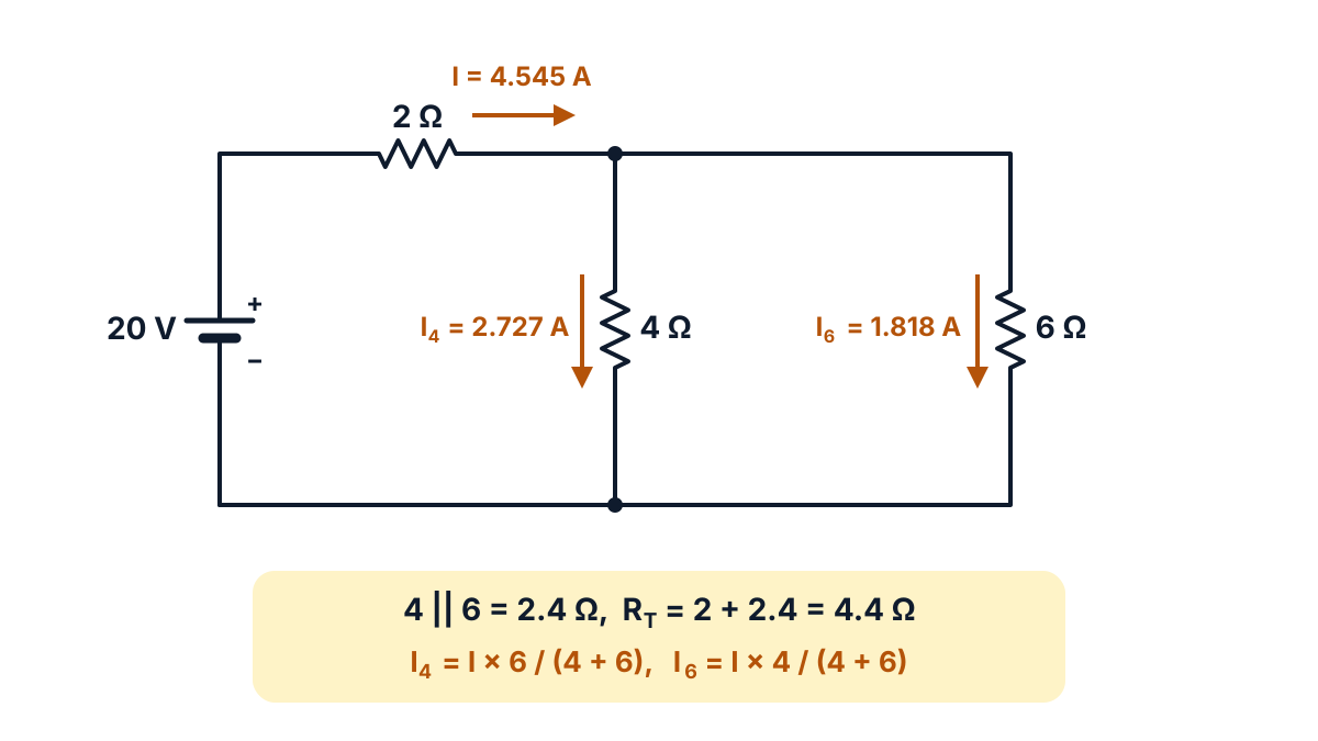
Figure Q12: the given circuit; the total current I divides between the 4 Ω and 6 Ω branches, and the smaller resistor takes the larger share.
- Parallel combination: RP = (4 × 6) / (4 + 6) = 24 / 10 = 2.4 Ω.
- Total resistance: RT = 2 + 2.4 = 4.4 Ω.
- Total current: I = V / RT = 20 / 4.4 = 4.545 A.
- Current division rule: for two resistors R₁ and R₂ in parallel, I₁ = I × R₂ / (R₁ + R₂) and I₂ = I × R₁ / (R₁ + R₂).
- Current in 4 Ω: I₄ = I × 6 / (4 + 6) = 4.545 × 0.6.
- Result: I₄ = 2.727 A.
- Current in 6 Ω: I₆ = I × 4 / (4 + 6) = 4.545 × 0.4.
- Result: I₆ = 1.818 A.
- Check (KCL): I₄ + I₆ = 2.727 + 1.818 = 4.545 A = I.
- Check (voltage): voltage across the parallel part = 4.545 × 2.4 = 10.91 V; I₄ × 4 = 10.91 V and I₆ × 6 = 10.91 V. The 2 Ω drops 9.09 V, and 9.09 + 10.91 = 20 V.
Answer: current through 4 Ω = 2.727 A; current through 6 Ω = 1.818 A (total current 4.545 A).
Q13. Calculate the current flowing through the galvanometer in the following Wheatstone bridge network : (10 marks)
Question (as printed): 13. Calculate the current flowing through the galvanometer in the following Wheatstone bridge network : 10
(Circuit printed on the paper: bridge ABCD with AB = 10 Ω carrying x, BC = 30 Ω carrying (x − z), AD = 20 Ω carrying y, DC = 15 Ω carrying (y + z), galvanometer G of 40 Ω from B to D carrying z, and a 2 V source between A and C; redrawn in the answer below.)
The “(x –z)” that the text layer of the paper prints below the figure is the current label of branch BC in the figure itself, not a separate instruction.
Understand it first
- A Wheatstone bridge is four resistors in a diamond, A-B-C-D. A source is joined across A and C. A galvanometer (G), a sensitive current meter, is joined across B and D.
- The bridge is balanced when no current flows through G. That happens when the ratios match: RAB / RBC = RAD / RDC.
- Here 10 / 30 = 0.333 but 20 / 15 = 1.333. The ratios differ, so the bridge is not balanced and some current flows in G.
- To find it, we use Kirchhoff’s laws with the branch current method (C-23 syllabus, Unit 2).
The two laws in simple words:
- KCL: current entering a junction = current leaving it. Charge cannot pile up.
- KVL: around any closed loop, the sum of EMFs = the sum of IR drops. Walk round a hill and back, and your total climb equals your total descent.
The paper has already named the currents for you using KCL. x enters B; z goes down through G; so (x − z) goes on to C. y enters D; z joins it from G; so (y + z) goes on to C.
There are three unknowns (x, y, z), so we need three loop equations. Pick two loops through the galvanometer and one through the battery. Then solve them step by step. A positive z means the current really flows from B to D, as assumed.
The same bridge idea, with a balance check and delta-star conversion, came in the Mar-Apr 2026 EE-106 paper.
Exam answer (10 marks)
Given: AB = 10 Ω, BC = 30 Ω, AD = 20 Ω, DC = 15 Ω, galvanometer BD = 40 Ω, supply 2 V across A (+) and C. Branch currents as marked on the paper: x, (x − z), y, (y + z), z.
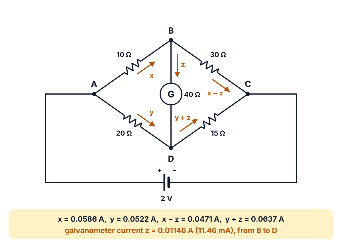
Figure Q13: the given bridge with the branch currents of the paper; KCL at B and D is already built into the labels (x − z) and (y + z).
- Balance check: 10/30 is not equal to 20/15, so the bridge is unbalanced and current flows in G.
- KVL, loop ABDA: 10x + 40z − 20y = 0, which simplifies to x − 2y + 4z = 0 … (i)
- KVL, loop BCDB: 30(x − z) − 15(y + z) − 40z = 0, which gives 30x − 15y − 85z = 0, or 6x − 3y − 17z = 0 … (ii)
- KVL, loop ADC and the battery: 20y + 15(y + z) = 2, which gives 35y + 15z = 2 … (iii)
- From (i): x = 2y − 4z.
- Put x in (ii): 6(2y − 4z) − 3y − 17z = 0, so 9y = 41z and y = 4.556z.
- Put y in (iii): 35 × 4.556z + 15z = 2, so 174.444z = 2 and z = 0.01146 A.
- Find y and x: y = 4.556 × 0.01146 = 0.0522 A; x = 2 × 0.0522 − 4 × 0.01146 = 0.0586 A.
- Other branches: x − z = 0.0471 A in BC and y + z = 0.0637 A in DC; total supply current x + y = 0.1108 A.
- Check (loop ABC and battery): 10x + 30(x − z) = 0.586 + 1.414 = 2.0 V, equal to the supply. Voltage across G = 40 × 0.01146 = 0.459 V.
Answer: current through the galvanometer z = 0.01146 A (about 11.46 mA), flowing from B to D. Exactly, z = 9/785 A.
Exam tip: keep the paper’s current labels. If you invent your own directions, KVL still works, but a negative answer then only means your guessed direction was opposite.
Q14. Calculate the monthly bill of a household consumer for the following loads in a month of 30 days if the cost of energy per unit is ₹3.50 (10 marks)
Question (as printed): 14. Calculate the monthly bill of a household consumer for the following loads in a month of 30 days if the cost of energy per unit is ₹3.50 10
(a) 4 lamps of 100 W each working for 6 hours a day
(b) 3 fans of 60 W each working for 10 hours a day
(c) An immersion heater of 2000 W is working for 1 hour a day
(d) An electric iron of 1000 W working for 1 hour a day
Understand it first
- The electricity board charges for energy, not power. Energy = power × time.
- With power in kilowatts and time in hours, energy is in kilowatt-hours (kWh). 1 kWh = 1 unit.
- A tariff is the price per unit. Here it is one flat rate, ₹3.50 for every unit.
Think of a water bill. The meter counts total litres used, not how fast the tap ran. A big heater for one hour can use as much as a small fan all day.
Plan of work:
- For each load: number × watts × hours per day = watt-hours per day.
- Add all loads. Divide by 1000 to get kWh per day.
- Multiply by 30 days to get units per month.
- Multiply by the rate to get the bill.
Check: the heater alone is 2 kW for an hour, so 2 units a day and 60 units a month. That is a big share for a short time.
The same kind of sum, with a slab tariff and a pump, came in the Mar-Apr 2025 EE-106 paper.
Exam answer (10 marks)
Given: loads (a) to (d) above, a 30 day month, rate ₹3.50 per unit (1 unit = 1 kWh).
- Formula: energy per day (Wh) = number × power (W) × hours per day; units = Wh / 1000.
- (a) Lamps: 4 × 100 × 6 = 2400 Wh per day.
- (b) Fans: 3 × 60 × 10 = 1800 Wh per day.
- (c) Immersion heater: 1 × 2000 × 1 = 2000 Wh per day.
- (d) Electric iron: 1 × 1000 × 1 = 1000 Wh per day.
- Total per day: 2400 + 1800 + 2000 + 1000 = 7200 Wh = 7.2 kWh.
- Energy per month: 7.2 × 30 = 216 units.
- Rate: ₹3.50 per unit.
- Bill: 216 × 3.50 = ₹756.
- Load-wise check: lamps 72, fans 54, heater 60 and iron 30 units; 72 + 54 + 60 + 30 = 216 units.
| Load | Wh per day | Units per month | Cost (₹) |
|---|---|---|---|
| 4 lamps, 100 W, 6 h | 2400 | 72 | 252 |
| 3 fans, 60 W, 10 h | 1800 | 54 | 189 |
| Immersion heater, 2000 W, 1 h | 2000 | 60 | 210 |
| Electric iron, 1000 W, 1 h | 1000 | 30 | 105 |
| Total | 7200 | 216 | 756 |
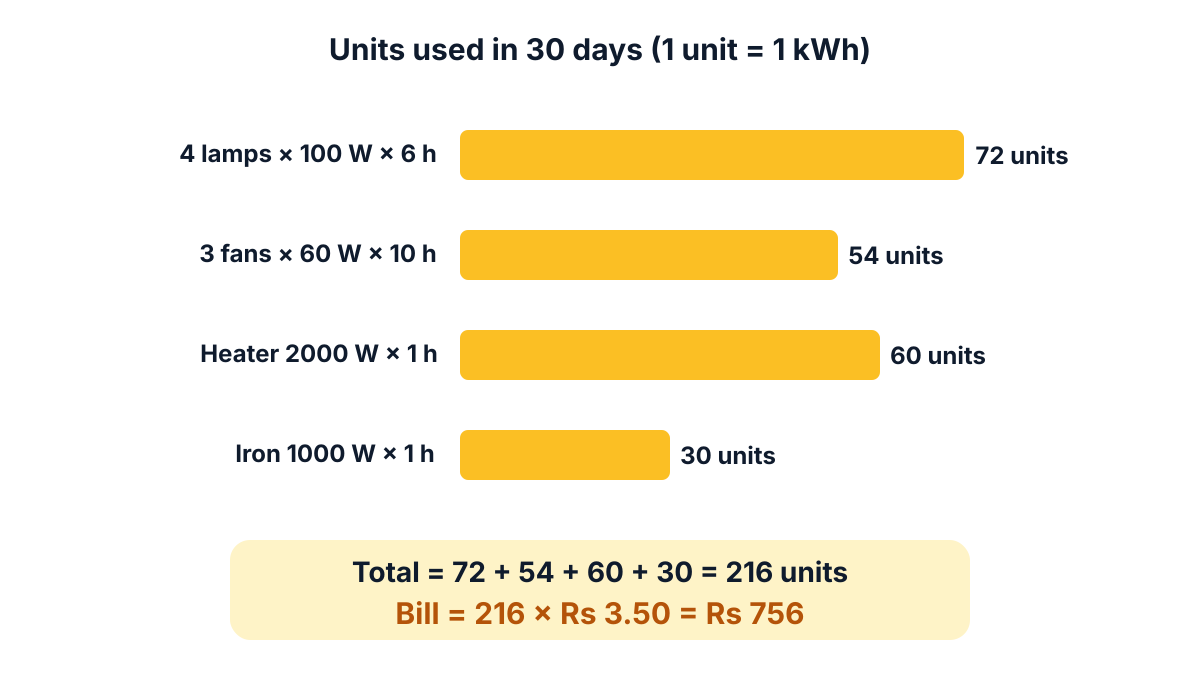
Figure Q14: units used by each load in 30 days; the total of 216 units at ₹3.50 gives ₹756.
Answer: energy = 216 units per month; monthly bill = ₹756.
Q15. An electric kettle rated at 1 kW, takes 7.5 minutes to bring 1 kg of water at 15 ºC to boiling point. (10 marks)
Question (as printed): 15. An electric kettle rated at 1 kW, takes 7.5 minutes to bring 1 kg of water at 15 ºC to boiling point. Find (a) efficiency of the kettle (b) current taken if the supply voltage is 230 V. 10
Understand it first
- A kettle has a heating element, a coil of high-resistance wire. Current through it makes heat by Joule’s law (Q6).
- The kettle takes electrical energy from the supply: input = power × time.
- Only part of it reaches the water. The rest warms the kettle body and escapes to the air.
- Efficiency (η, eta) = useful output ÷ input. Here the useful output is the heat taken by the water.
The heat needed to warm water depends on three things:
- Mass (m): more water needs more heat.
- Temperature rise (Δθ): from 15 °C to the boiling point, 100 °C, is a rise of 85 °C.
- Specific heat (c): the heat needed to warm 1 kg by 1 °C. For water it is 1 kcal, which is 4186 J, as the same open physics chapter defines the kilocalorie.
So heat to water H = m × c × Δθ.
Think of filling a leaky bucket. The tap sends 100 litres, but only about 79 stay in the bucket. Efficiency is 79 out of 100.
Time must be in seconds, because 1 W = 1 J per second: 7.5 minutes = 7.5 × 60 = 450 s.
For part (b), the kettle is rated 1 kW at the supply voltage. Since P = V × I, the current is I = P / V.
Exam answer (10 marks)
The paper does not print the split for (a) and (b). This answer takes 7 marks for (a) and 3 marks for (b).
(a) Efficiency of the kettle (7 marks).
- Given: P = 1 kW = 1000 W; t = 7.5 min = 7.5 × 60 = 450 s; m = 1 kg; θ₁ = 15 °C; θ₂ = 100 °C (boiling point of water).
- Specific heat: c = 4186 J per kg per °C (1 kcal per kg per °C).
- Temperature rise: Δθ = 100 − 15 = 85 °C.
- Heat taken by water (output): H = m c Δθ = 1 × 4186 × 85 = 355810 J (85 kcal).
- Electrical energy input: W = P × t = 1000 × 450 = 450000 J.
- Efficiency formula: η = output / input = H / W.
- Result: η = 355810 / 450000 = 0.7907 = 79.07%.
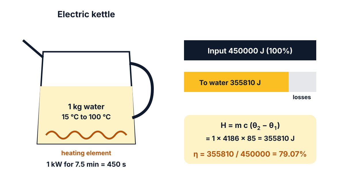
Figure Q15: of the 450000 J taken from the supply, 355810 J reaches the water; the rest is lost, so η = 79.07%.
(b) Current taken (3 marks).
- Formula: P = V × I, so I = P / V.
- Substitution: I = 1000 / 230.
- Result: I = 4.348 A.
Answer: (a) efficiency = 79.07%; (b) current = 4.348 A.
Exam tip: change 7.5 minutes into 450 seconds before you find the input energy. Using minutes gives a wrong efficiency.
Q16. Develop the transformation formulae for converting Delta configuration into Star configuration. (10 marks)
Question (as printed): 16. Develop the transformation formulae for converting Delta configuration into Star configuration. 10
Understand it first
- In a delta (Δ) connection, three resistors form a triangle. Each sits directly between two terminals, A, B and C.
- In a star (Y) connection, three resistors meet at one centre point N. Their outer ends are the terminals A, B and C.
- Some networks, like the bridge in Q13, have no resistors in plain series or parallel. Swap a delta for a star, and the series and parallel rules work again.
Two shapes are equivalent when a meter cannot tell them apart. Picture a sealed box with only the three terminals showing. Measure the resistance between each pair with a meter. If all three readings are the same for both boxes, you cannot tell which shape is inside.
How the derivation works, in plain words:
- Write the resistance between A and B in both networks and set them equal. Do the same for B-C and C-A. That gives three equations.
- In the delta, between A and B, RAB sits in parallel with the path RBC + RCA. In the star, the path is simply RA + RB in series.
- Subtract and add the equations so that two of the star arms cancel. One arm is left alone.
Memory aid: each star arm = (product of the two delta resistors that touch its terminal) ÷ (sum of all three). If all three delta resistors are equal (R), each star arm is R/3.
The reverse change, star to delta, was asked in the Mar-Apr 2025 EE-106 paper; learn both, because the board alternates them.
Exam answer (10 marks)
Delta-to-star transformation replaces the delta resistors RAB, RBC, RCA between terminals A, B, C with three star resistors RA, RB, RC meeting at a common point N.
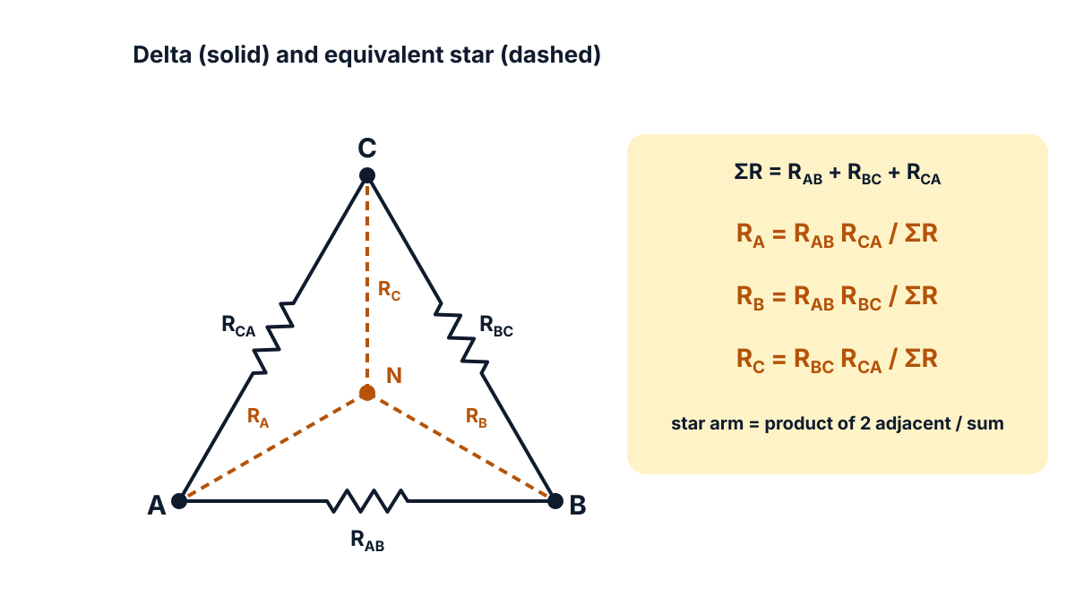
Figure Q16: delta RAB, RBC, RCA (solid) and the equivalent star RA, RB, RC at N (dashed); each star arm uses the two delta resistors that meet at its terminal.
- Condition: the networks are equivalent when the resistance between any two terminals, with the third open, is the same in both. Let ΣR = RAB + RBC + RCA.
- Between A and B: RA + RB = RAB (RBC + RCA) / ΣR … (1)
- Between B and C: RB + RC = RBC (RCA + RAB) / ΣR … (2)
- Between C and A: RC + RA = RCA (RAB + RBC) / ΣR … (3)
- Subtract (2) from (1): RA − RC = (RAB RCA − RBC RCA) / ΣR … (4)
- Add (3) and (4): 2RA = (RCA RAB + RCA RBC + RAB RCA − RBC RCA) / ΣR = 2 RAB RCA / ΣR.
- Star arm at A: RA = RAB RCA / (RAB + RBC + RCA).
- Star arm at B (in the same way, (1) − (3) added to (2)): RB = RAB RBC / (RAB + RBC + RCA).
- Star arm at C ((2) − (1) added to (3)): RC = RBC RCA / (RAB + RBC + RCA).
- Rule and special case: each star resistor = product of the two delta resistors meeting at that terminal ÷ sum of the three delta resistors. For a balanced delta (all equal to R), each star resistor = R/3.
Q17. Using Thevenin’s theorem, find the current through 8 Ω resistance in the circuit shown below : (10 marks)
Question (as printed): 17. Using Thevenin’s theorem, find the current through 8 Ω resistance in the circuit shown below : 10
(Circuit printed on the paper: a 40 V source, 3 Ω in series, 6 Ω across, then 5 Ω in series to the 8 Ω load; redrawn in the answer below.)
Understand it first
Thevenin’s theorem says: however complicated the circuit, the load only “feels” one voltage and one resistance in series. So you replace everything except the load with one battery and one resistor.
- VTH (Thevenin voltage) is the voltage across the load terminals A and B when the load is taken out. This is the open-circuit voltage. Nothing is connected, so no current flows out of A and B.
- RTH (Thevenin resistance) is the resistance seen looking back into A and B, with the sources switched off.
- “Switching off” an ideal voltage source means replacing it with a plain wire (a short), because its internal resistance is zero.
- The load current is then IL = VTH / (RTH + RL).
Think of a wall socket. To the appliance, the power station and lines behind it look like one source with a little resistance.
How to read this circuit: with the 8 Ω removed, the 5 Ω carries no current, so it has no voltage drop. Then VTH is simply the voltage across the 6 Ω. With the source shorted, the 3 Ω and 6 Ω come in parallel, and the 5 Ω adds in series.
A similar Thevenin sum, with the same kind of ladder circuit, came in the Mar-Apr 2026 EE-106 paper.
Exam answer (10 marks)
Given: 40 V source, 3 Ω in series, 6 Ω across, 5 Ω in series to the load; load RL = 8 Ω across A-B.
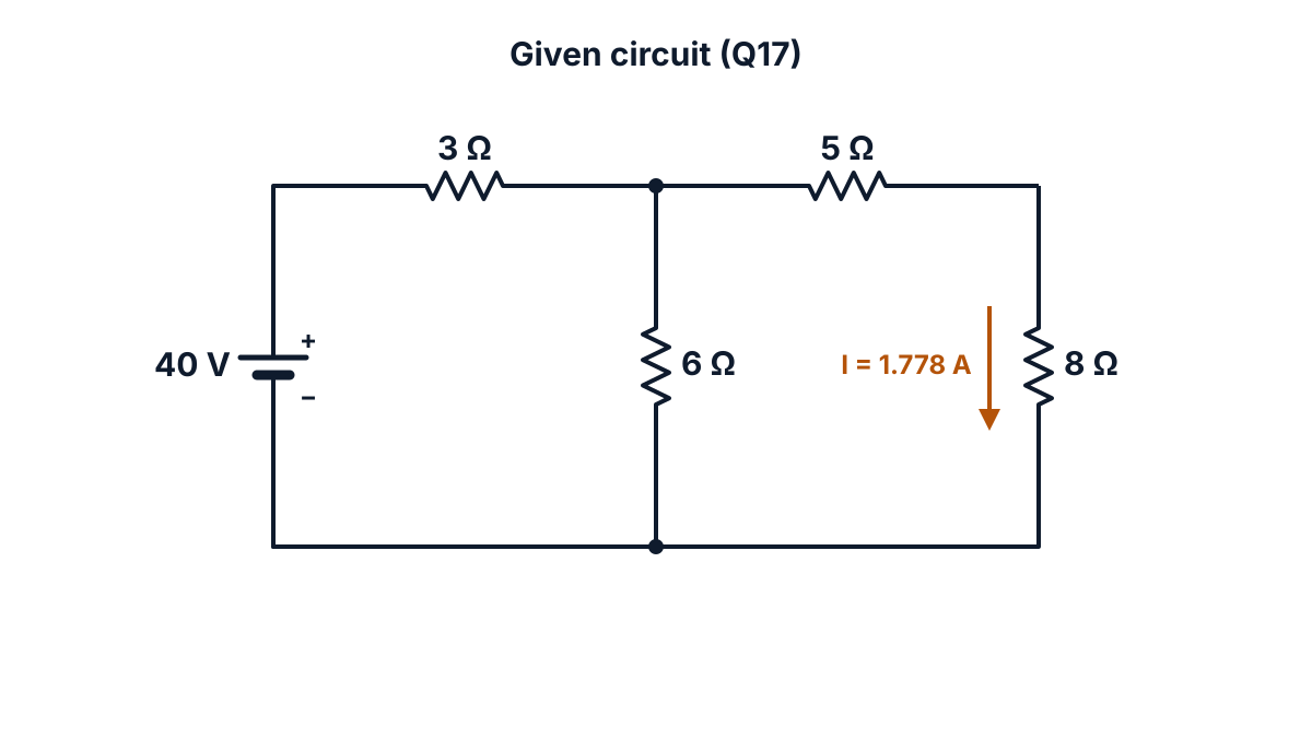
Figure Q17 (given circuit): 40 V source with 3 Ω, 6 Ω and 5 Ω feeding the 8 Ω load.
- Thevenin’s theorem: any linear two-terminal network can be replaced, as seen from the load terminals A and B, by one voltage source VTH in series with one resistance RTH; then IL = VTH / (RTH + RL).
- Remove the load: take out the 8 Ω and mark its terminals A and B.
- Open-circuit current: no current flows in the 5 Ω, so the 40 V drives the 3 Ω and 6 Ω in series: I = 40 / (3 + 6) = 4.444 A.
- VTH: voltage across the 6 Ω = 4.444 × 6 = 26.67 V (that is, 40 × 6 / 9).
- Kill the source: replace the 40 V source by a short circuit.
- Parallel part: 3 Ω ∥ 6 Ω = (3 × 6) / (3 + 6) = 18 / 9 = 2 Ω.
- RTH: 2 + 5 = 7 Ω.
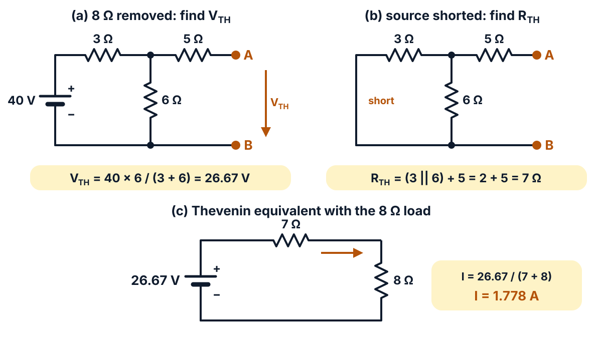
Figure Q17 (steps): (a) finding VTH, (b) finding RTH, (c) the Thevenin equivalent with the 8 Ω load.
- Thevenin equivalent: 26.67 V in series with 7 Ω, feeding RL = 8 Ω.
- Load current: IL = 26.67 / (7 + 8) = 26.67 / 15.
- Result and check: IL = 1.778 A. A node-voltage check gives 23.11 V at the junction of 3 Ω, 6 Ω and 5 Ω, and 23.11 / (5 + 8) = 1.778 A.
Answer: current through the 8 Ω resistance = 1.778 A.
Q18. Find the value of RL for which maximum power will be absorbed in it and determine the maximum power in the circuit shown below : (10 marks)
Question (as printed): 18. Find the value of RL for which maximum power will be absorbed in it and determine the maximum power in the circuit shown below : 10
(Circuit printed on the paper: a 36 V source, 3 Ω in series, 6 Ω across, then 4 Ω in series to the load RL; redrawn in the answer below.)
Understand it first
- By Thevenin’s theorem (Q17), the circuit seen from RL is one source VTH in series with RTH.
- If RL is very small, a big current flows but the voltage across RL is tiny. Power (V × I) is small.
- If RL is very large, the voltage across it is big but almost no current flows. Power is small again.
- In between, the power is highest. The maximum power transfer theorem says this happens when RL = RTH.
So the method is: find VTH and RTH exactly as in Q17. Set RL = RTH. Then Pmax = VTH² / (4 RL).
The “4” comes from the current. At RL = RTH, the current is VTH / (2RL). Power = I² RL = VTH² / (4RL).
Try a few loads for this circuit (VTH = 24 V, RTH = 6 Ω), using P = I² RL:
| RL | Current | Power in RL |
|---|---|---|
| 2 Ω | 3 A | 18 W |
| 6 Ω (= RTH) | 2 A | 24 W |
| 12 Ω | 1.333 A | 21.33 W |
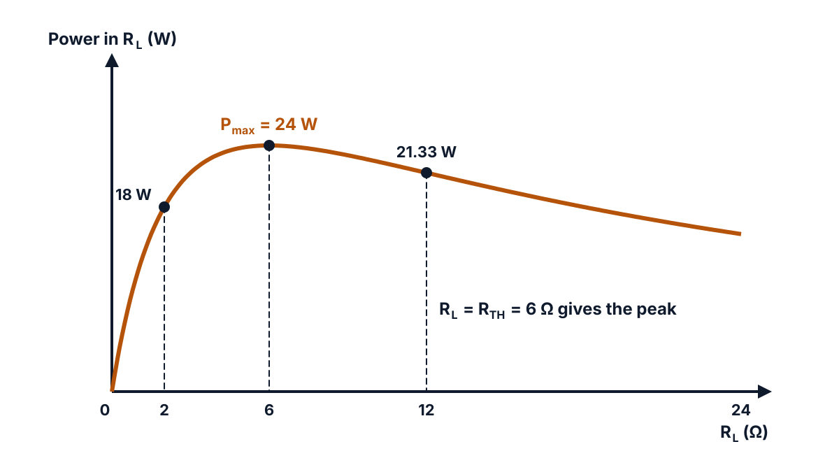
Figure Q18 (power curve): power in RL rises to a peak of 24 W at RL = 6 Ω and falls on both sides.
At maximum power, half of the power is lost inside RTH, so the efficiency is only 50%. That is why the theorem is used in electronic and communication circuits, not in power supply lines.
Exam answer (10 marks)
Given: 36 V source, 3 Ω in series, 6 Ω across, 4 Ω in series to the load RL.
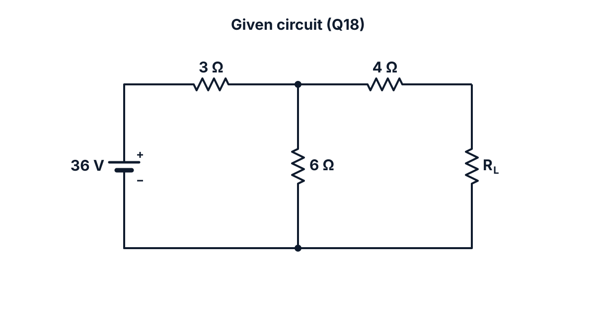
Figure Q18 (given circuit): 36 V source with 3 Ω, 6 Ω and 4 Ω feeding the variable load RL.
- Maximum power transfer theorem: a load receives maximum power from a linear DC network when its resistance equals the Thevenin resistance of the network seen from the load terminals: RL = RTH.
- Remove RL: mark the load terminals A and B and leave them open.
- Open-circuit current: no current flows in the 4 Ω, so I = 36 / (3 + 6) = 4 A through the 3 Ω and 6 Ω.
- VTH: voltage across the 6 Ω = 4 × 6 = 24 V.
- Kill the source: short the 36 V source; 3 Ω ∥ 6 Ω = 18 / 9 = 2 Ω.
- RTH: 2 + 4 = 6 Ω.
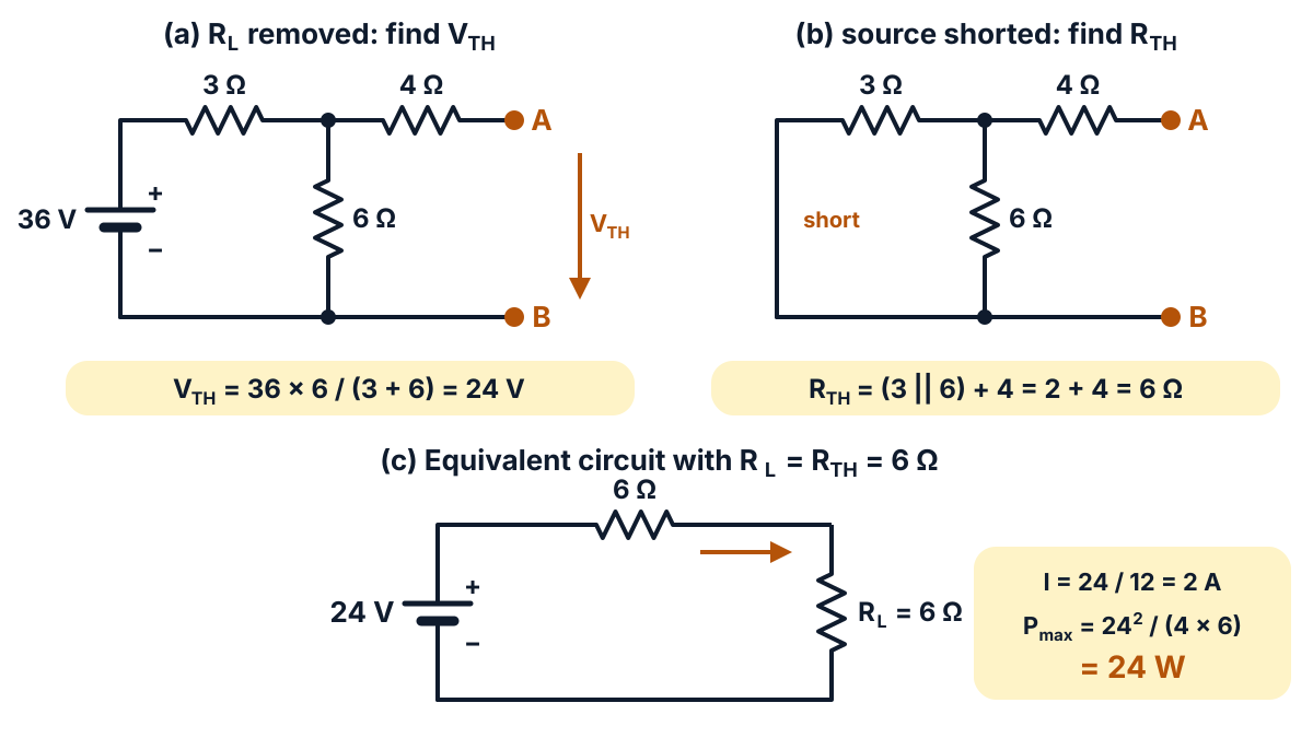
Figure Q18 (steps): (a) finding VTH, (b) finding RTH, (c) the equivalent circuit with RL = RTH = 6 Ω.
- Value of RL for maximum power: RL = RTH = 6 Ω.
- Load current: IL = VTH / (RTH + RL) = 24 / (6 + 6) = 2 A.
- Maximum power: Pmax = IL² × RL = 2² × 6 = 24 W.
- Check by formula: Pmax = VTH² / (4 RL) = 24² / (4 × 6) = 576 / 24 = 24 W. The voltage across RL is 12 V, half of VTH.
Answer: RL = 6 Ω for maximum power; maximum power = 24 W.
Exam tip: do not leave out the 4 Ω when you find RTH. It is in series with the load terminals, so RTH = (3 ∥ 6) + 4, not 3 ∥ 6.
FAQ
Which units carry the most marks in the EE-106 October 2025 paper?
Unit 3 (work, power, energy and heating) carries 29 marks: Q5, Q6, Q7, Q14 and Q15. Unit 5 (network theorems) carries 26 marks: Q9, Q10, Q17 and Q18. Together they are more than two thirds of the 80 marks.
Which five Part B questions should I choose in this paper?
Q12, Q14, Q17, Q18 and Q11 are the safest five. Each is a short calculation with one clear method. Q13 is also fine if you are quick with three simultaneous equations, and Q16 is a fixed derivation you can learn by heart.
What does (x – z) under the Q13 figure mean?
It is not a misprint. It is the current label of the 30 Ω branch BC, which slipped out of the figure in the text layer of the paper. By KCL at B, the current x splits into z through the galvanometer and (x − z) through BC.
Which specific heat should I use for water in the kettle sum (Q15)?
Use 4186 J per kg per °C, which is the same as 1 kcal per kg per °C, and take the boiling point as 100 °C. Then the heat given to 1 kg of water from 15 °C is 355810 J and the efficiency comes to 79.07%.
Sources
- AP SBTET C-23 DEEE EE-106 question paper, Oct-Nov 2025
- C-23 Curriculum, Diploma in Electrical and Electronics Engineering, SBTET AP
- Reference books (C-23 syllabus):
- B.L. Theraja: Electrical Technology Vol. 1, S. Chand
- V.K. Mehta: Introduction to Electrical Engineering
- J.B. Gupta: A Course in Electrical Technology, Katson Books
- G.B. Bharadwajan & A. Subba Rao: Elements of Electrical Engineering
- William H. Hayt: Engineering Circuit Analysis, Tata McGraw-Hill
- Heat and the mechanical equivalent of heat, open college physics text
Writes and reviews the SBTET EEE Papers solutions: AP SBTET diploma question papers answered step by step from the prescribed syllabus.