EE-107 Engineering Drawing Oct-Nov 2025 paper solved: hexagonal pyramid on VP, section of a hexagonal prism and orthographic views
 Nookesh Karri ·· 41 min read

This post solves the AP SBTET C-23 first year engineering drawing question paper October 2025 (EE-107, October/November 2025 board exam). It answers all 4 Part A questions and all 6 Part B questions. Each question starts with the idea in simple words, then the exam answer: numbered steps of construction and the finished drawing, drawn to scale from computed points. You can open the original question paper PDF next to this page and check every question and figure.
Engineering Drawing question paper October 2025: pattern and syllabus chapters
The EE-107 Engineering Drawing paper of October 2025 is a common first year paper for many branches (its code line reads C23-AEI/AIM/AI/BM/CH/CHST/CHOT/CHPC/CHPP/CM/CAI/CIOT/ CCB/CCN/EE/EEVT/EC/ECII/ TT, 107). It is 3 hours long and carries 60 marks. Part A has 4 questions of 5 marks each (20 marks, all compulsory). Part B has 6 questions of 10 marks each, and you answer any four (40 marks).
The paper does not print marks beside the questions; they come from the instructions. The questions follow the chapter blueprint of the C-23 curriculum exactly: 2, 1, 1, 0 and 0 short questions and 0, 1, 2, 1 and 2 essay questions from Chapters 1 to 5.
Part A instructions as printed on the paper (PART—A, 5×4=20):
Instructions : (1) Answer all questions.
(2) Each question carries five marks.
(3) All the dimensions are in mm.
Part B instructions as printed on the paper (PART—B, 10×4=40):
Instructions : (1) Answer any four questions.
(2) Each question carries ten marks.
(3) All the dimensions are in mm.
| Q no | Topic | Syllabus chapter | Marks |
|---|---|---|---|
| 1 | Vertical capital letters, 10 mm | Ch 1 Drawing instruments, lettering and dimensioning | 5 |
| 2 | Redraw a figure in parallel dimensioning | Ch 1 | 5 |
| 3 | Hexagon of side 40 by the general method | Ch 2 Geometric constructions | 5 |
| 4 | Projections of two points | Ch 3 Projections of points, lines, planes and solids | 5 |
| 5 | Cycloid of a circle of diameter 60 | Ch 2 | 10 |
| 6 | Line inclined to HP, parallel to VP | Ch 3 | 10 |
| 7 | Hexagonal pyramid resting on VP | Ch 3 | 10 |
| 8 | Section of a hexagonal prism, plane parallel to VP | Ch 4 Sectional views | 10 |
| 9 | Front, top and right side views of a stepped block | Ch 5 Orthographic projection | 10 |
| 10 | Front and top views of a base with two uprights | Ch 5 | 10 |
The paper has a few printing slips: “is inclines” in Q6, no instruction in Q7, “rests at with” in Q8, and a 2+2 split printed in the five-mark Q4. The questions below copy them exactly. None of them changes what you draw.
How this post draws. Every figure is drawn to scale from computed points, and each caption gives the drawing scale. Scale 1:1 (full size) means 1 mm on paper shows 1 mm on the object; scale 1:2 would mean 1 cm on paper shows 2 cm on the object. Every answer drawing in this paper fits an A3 sheet at 1:1. In the drawings, thick lines are visible edges. Thin lines are construction lines and projectors. Dashed lines are hidden edges, and chain lines (long dash, dot) are centre lines and cutting planes.
My advice: in Part B, pick Q5, Q6 and Q10 first. The cycloid and the inclined line have short fixed steps, and Q10 asks for only two views. For the fourth, take Q7 if you know solids, or Q9 if you can place a right side view. Q8 is quick too, because a plane parallel to VP shows the cut face in true shape in the front view itself.
You can see every Engineering Drawing session on the Engineering Drawing subject page.
Q1. Write the following using vertical capital letters of 10 mm size : (5 marks)
Question (as printed):
- Write the following using vertical capital letters of 10 mm size : “KEEPING LOW AIM IS A CRIME”
Understand it first
- Lettering means writing titles, notes and numbers on a drawing by hand, in a fixed neat style.
- Capital means upper-case letters only. Vertical means the letters stand straight up, at 90° to the guide line. (Sloped letters lean to the right at 75°.)
- Freehand letters on a drawing are single stroke letters. Each part of a letter is one stroke of the pencil, as thick as the pencil point. You do not draw a hollow outline and fill it.
- 10 mm size means the height h of every capital letter is 10 mm.
- Guide lines are two thin, light lines drawn 10 mm apart. Every letter sits on the lower line and touches the upper line. They keep all letters the same height.
- The BIS code SP 46 gives the proportions of “type B” lettering as fractions of h. For h = 10 mm these are:
- line width d = h/10 = 1 mm,
- gap between letters a = 2h/10 = 2 mm,
- gap between words e = 6h/10 = 6 mm,
- pitch between two lines of capital text b = 13h/10 = 13 mm.
- The width of a letter is not one fixed number. Most letters here are about 6 mm wide. M and W are wider (about 8 mm), E is a little narrower (about 5 mm), and I is a single line.
It works like a ruled notebook: the lines keep every letter the same size, even when you write fast. Lettering came in both earlier papers too, in the EE-107 October 2024 paper and the EE-107 March 2025 paper, with different titles.
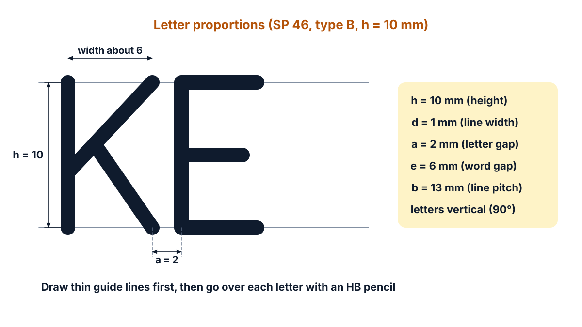
Figure Q1a: lettering proportions for h = 10 mm (type B): height 10, line width 1, letter gap 2, word gap 6.
Exam answer (5 marks)
Steps:
- Guide lines: draw two thin horizontal guide lines 10 mm apart with a sharp 2H pencil, long enough for the whole sentence.
- Spacing: plan the sentence: about 6 mm per letter (8 mm for M and W), a 2 mm gap between letters and a 6 mm gap between words. The 21 letters and 5 word gaps come to about 166 mm, which fits on the sheet in one line.
- Letters: draw each capital letter upright (90° to the guide line), touching both guide lines, with single strokes. Draw the round letters G, O, S, C and R with smooth curves.
- Line width: go over every letter with an HB pencil so that all strokes have the same thickness, about 1 mm (h/10).
- Finish: check that the line reads “KEEPING LOW AIM IS A CRIME”, with uniform height, width and spacing, and leave the guide lines faint.
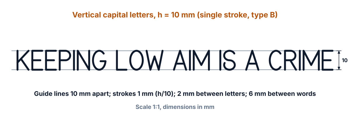
Figure Q1b: the sentence in vertical capital letters, h = 10 mm (drawn to scale; draw it full size (scale 1:1) on your sheet, all dimensions in mm).
Key points to write: guide lines 10 mm apart; capital, upright, single stroke; uniform 1 mm strokes; 2 mm between letters, 6 mm between words.
Q2. Redraw the following figure in parallel dimensioning method : (5 marks)
Question (as printed): 2. Redraw the following figure in parallel dimensioning method :
[Figure: a stepped plate. Chain dimensions 20, 20, 20 along the top and 20, 20, 20 down the right side.]
Understand it first
- Dimensioning means writing the sizes on a drawing with dimension lines, extension lines, arrowheads and numbers.
- An extension line is a thin line that comes out from the object. A dimension line is a thin line with a filled arrowhead at each end. The number sits above it.
- Chain dimensioning (the given figure) puts the sizes one after another: 20, then the next 20 starts where the first ended, and so on.
- Parallel dimensioning measures every size from one common edge, called the datum. The dimension lines are parallel to one another, the shortest one nearest the object.
- Why it matters: in a chain, a small error in each step adds up. From a datum, each size is checked on its own.
- Reading this figure: the plate is 60 wide and 60 high. The top is 20 wide. Two steps of 20 × 20 come down to the right.
- So the widths from the left edge are 20, 40 and 60. The heights from the bottom edge are 20, 40 and 60.
Think of marking a wall for three shelves. If you measure every shelf from the floor, one wrong mark does not shift the others.
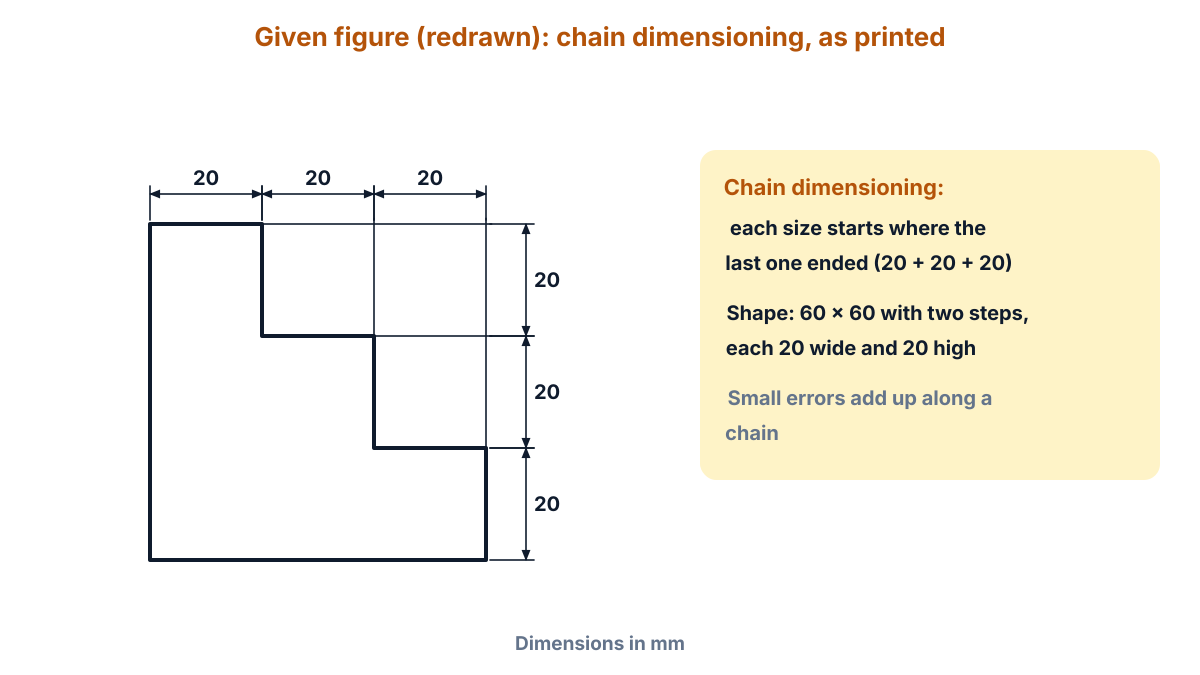
Figure Q2a: given figure (redrawn) with its chain dimensions, as printed.
Exam answer (5 marks)
Steps:
- Outline: draw the plate full size with thick lines: bottom 60, left side 60, top 20, then steps down 20 and across 20 twice to the right edge, which is 20 high.
- Datums: take the left edge as the datum for widths and the bottom edge as the datum for heights.
- Horizontal dimensions: above the plate draw three parallel dimension lines, all starting at the left edge: 20 (nearest, about 10 mm above), then 40 and 60, about 8 mm apart.
- Vertical dimensions: to the right draw three parallel dimension lines, all starting at the bottom edge: 20 (nearest), then 40 and 60.
- Finish: draw thin extension lines from each corner, filled arrowheads, and write each number above its line, reading from the bottom or from the right.
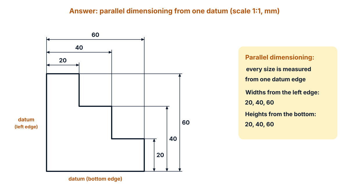
Figure Q2b: answer in parallel dimensioning from the left and bottom datums (drawn to scale; draw it full size (scale 1:1) on your sheet, all dimensions in mm).
Key points to write: one datum for each direction; dimension lines parallel, shortest nearest; 20, 40, 60 from the left edge and from the bottom edge; thin lines, filled arrowheads. The October 2024 solution also used parallel dimensioning on a different figure.
Q3. Draw a regular polygon which is having six equal sides with the length of 40 mm using general method. (5 marks)
Question (as printed): 3. Draw a regular polygon which is having six equal sides with the length of 40 mm using general method.
Understand it first
- A polygon with six equal sides and six equal angles is a regular hexagon.
- The exterior angle of any regular polygon is 360° ÷ n, where n is the number of sides. For a hexagon it is 360° ÷ 6 = 60°.
- The interior angle is 180° minus the exterior angle: 180° − 60° = 120°.
- The general method works for any number of sides. You draw a semicircle with radius equal to the side and divide it into n equal parts. Each part is 180° ÷ n.
- Two parts make 2 × (180° ÷ n) = 360° ÷ n, which is the exterior angle. So the line to division 2 always makes the interior angle with the first side. That is why the rule is “always join to point 2”.
- The other corners come from rays through divisions 3, 4 and 5 and arcs of the side length.
Walk round a six-sided park. You turn the same 60° at every corner, and after 6 turns you are back at the start. The March 2025 paper asked the same construction with a side of 30.
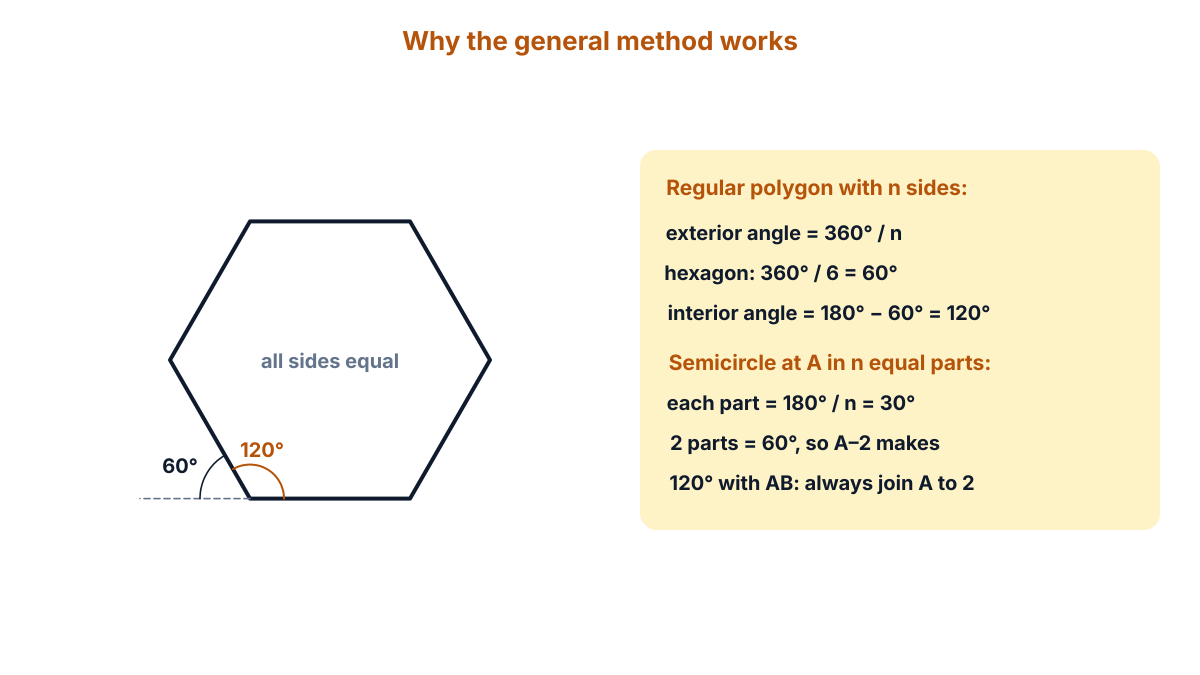
Figure Q3a: why the general method works: two of the six equal parts give the 60° exterior angle.
Exam answer (5 marks)
Steps:
- Side AB: draw AB = 40 mm and extend BA beyond A to P.
- Semicircle: with A as centre and radius 40, draw a semicircle from P to B. Divide it into 6 equal parts (30° each) and number them 1 to 5 from P.
- Side AF: join A to point 2. A–2 is the side AF (40 long, at 120° to AB).
- Rays: join A to points 3, 4 and 5 and extend these rays.
- Corners: with B as centre and radius 40, cut ray A–5 at C. With C as centre, cut ray A–4 at D. With F as centre, cut ray A–3 at E. Join B, C, D, E and F to complete the hexagon ABCDEF.
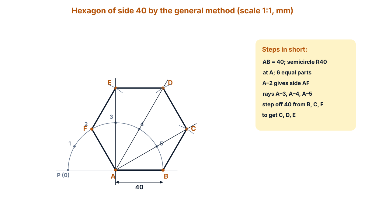
Figure Q3b: hexagon ABCDEF of side 40 by the general method (drawn to scale; draw it full size (scale 1:1) on your sheet, all dimensions in mm).
Answer: a regular hexagon ABCDEF with all sides 40 mm and all angles 120°; across the flats it measures 69.28 mm and across the corners 80 mm (a check, not a step).
Q4. Draw the projections of the following points on a common reference line : (5 marks)
Question (as printed): 4. Draw the projections of the following points on a common reference line : 2+2
(a) Point A 35 mm above HP and 40 mm infront of VP.
(b) Point B on HP and 50 mm infront of VP.
The paper prints the split 2+2, which adds up to 4, but the instructions give five marks to each Part A question. This answer gives (a) and (b) two points each and one point for the common XY line.
Understand it first
- H.P. is the horizontal plane, like the floor. V.P. is the vertical plane, like a wall behind the object.
- The two planes meet in a line called the XY line (the reference line). “A common reference line” means both points are drawn on one XY line, side by side.
- In first angle projection, the object sits in front of the VP and above the HP. The object is between you and the plane.
- The front view is drawn on the VP. Its point gets a dash: a’. The top view is drawn on the HP. Its point has no dash: a.
- After drawing, the HP is turned down by 90° about XY. So on paper, the front view is above XY and the top view is below it. Both lie on one vertical line, the projector.
- The height above HP sets how far a’ is above XY. The distance in front of VP sets how far a is below XY.
- A point on HP has zero height. So its front view b’ lies on XY itself.
Stand a pencil tip in the air in front of a wall. Its shadow on the wall shows its height. Its shadow on the floor shows how far it is from the wall.
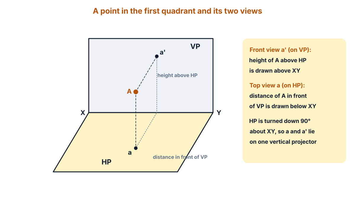
Figure Q4a: a point A in the first quadrant, its front view a’ on VP and its top view a on HP.
Exam answer (5 marks)
Steps:
- XY line: draw one horizontal reference line XY, long enough for both points.
- (a) Front view: at a convenient place, draw a vertical projector and mark a’ 35 mm above XY.
- (a) Top view: on the same projector mark a 40 mm below XY.
- (b) Front view: further along XY draw a second projector. B is on HP, so mark b’ on XY.
- (b) Top view: on that projector mark b 50 mm below XY. Label a’, a, b’, b and write the distances 35, 40 and 50.
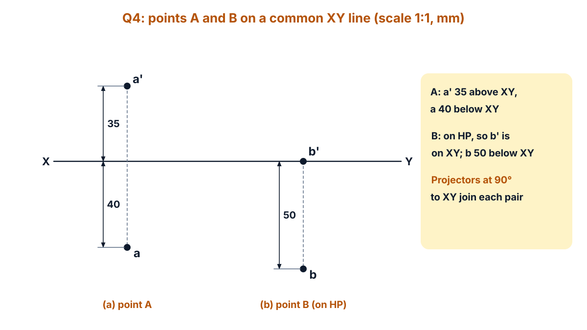
Figure Q4b: points A and B on a common XY line (drawn to scale; draw it full size (scale 1:1) on your sheet, all dimensions in mm).
Answer: (a) a’ 35 mm above XY and a 40 mm below XY on one projector; (b) b’ on XY and b 50 mm below XY on another projector.
Q5. Construct a cycloid for a circle with a diameter of 60 mm. (10 marks)
Understand it first
- A cycloid is the path traced by a point on the rim of a circle when the circle rolls along a straight line without slipping.
- The circle that rolls is the generating circle. Here its diameter D is 60 mm, so its radius is 30 mm.
- In one full turn the circle rolls a distance equal to its circumference: πD = π × 60 = 188.50 mm. So the base line is 188.5 mm long.
- The centre of the circle moves along a straight line 30 mm above the base line. We call it the locus of the centre.
- We divide both the circle and the centre line into 12 equal parts. Each part of the line is 188.5 ÷ 12 = 15.71 mm. Each part of the circle is 360° ÷ 12 = 30°.
- When the centre reaches C₁, the circle has turned 30°. The point P has risen to the height of division 1 of the circle. So P₁ is on the horizontal line through division 1, at 30 mm from C₁.
- The same rule gives P₂ to P₁₁. The point reaches the top (60 mm high) at half a turn, and touches the base line again at P₁₂.
Put a chalk mark on a bicycle tyre and roll the cycle forward. The mark rises, goes over the top and comes down again in one arch for every turn of the wheel. The October 2024 paper asked a cycloid too.
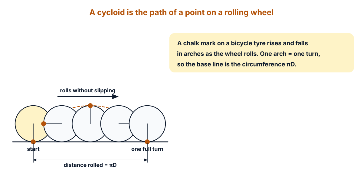
Figure Q5a: a point on a rolling circle traces one arch per turn; the base equals the circumference πD.
Exam answer (10 marks)
Steps of construction:
- Circle: draw the generating circle of diameter 60 mm with centre C, touching a horizontal line at P.
- Base line: from P draw the base line PP₁₂ = πD = 188.5 mm.
- Divide the circle: divide the circle into 12 equal parts (30° each) and number them 1 to 11, starting from P and going clockwise.
- Centre line: through C draw a line parallel to the base line, 188.5 mm long. Divide it into 12 equal parts of 15.71 mm and mark C₁ to C₁₂.
- Horizontal lines: through the points 1 to 11 on the circle draw thin lines parallel to the base line.
- First points: with C₁ as centre and radius 30, cut the line through point 1 at P₁. With C₂ as centre, cut the line through point 2 at P₂.
- More points: in the same way, with centres C₃ to C₁₁ and radius 30, cut the lines through points 3 to 11 at P₃ to P₁₁.
- End point: P₁₂ is the end of the base line, where the circle centred at C₁₂ touches it.
- Curve: join P, P₁, P₂ … P₁₂ with a smooth freehand curve (or a French curve).
- Check and finish: the top point P₆ must be 60 mm above the base line, above C₆. Make the curve thick, keep the construction lines thin, and label the base line πD = 188.5.
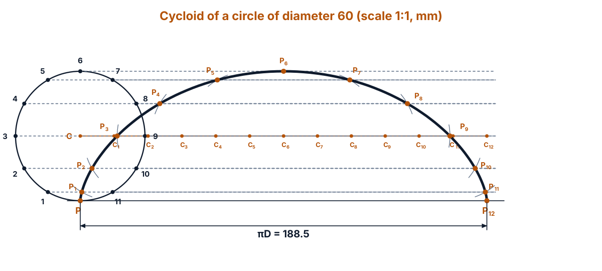
Figure Q5b: cycloid of a circle of diameter 60 on a base of 188.5 (drawn to scale; draw it full size (scale 1:1) on your sheet, all dimensions in mm).
Answer: one arch of a cycloid on a base line 188.5 mm long, 60 mm high at P₆, with P₁ to P₁₁ found by arcs of radius 30 from C₁ to C₁₁.
Exam tip: each arc is cut on the horizontal line of the same number (C₄ cuts line 4). Using the wrong line gives a lopsided curve.
Q6. A line AB of length 60 mm is inclines at 40° to HP and parallel to VP. (10 marks)
Question (as printed): 6. A line AB of length 60 mm is inclines at 40° to HP and parallel to VP. The end point A of line is 30 mm above HP and 35 mm infront of VP. Draw its projections.
“Is inclines” is a misprint for “is inclined”.
Understand it first
- AB is a straight line 60 mm long. This is its true length (TL), its real length.
- Parallel to VP means the line is at the same distance from the wall all along. A line parallel to a plane shows its true length and its true angle on that plane. So the front view a’b’ is 60 mm long and makes 40° with XY.
- Inclined at 40° to HP means the line rises at 40° from the floor. Its top view is shorter than the true length: 60 × cos 40° = 45.96 mm.
- The line is the same distance from VP all along. So the top view ab is parallel to XY.
- “A is 30 mm above HP” puts a’ 30 mm above XY. “35 mm in front of VP” puts a 35 mm below XY. Since the whole line is 35 mm from VP, ab lies on a line 35 mm below XY.
- End B rises by 60 × sin 40° = 38.57 mm. So b’ is 30 + 38.57 = 68.57 mm above XY.
Lean a 60 cm ruler against a box at 40°, with its flat face towards you. From the front you see the full ruler at 40°. From above you see a shorter, level line.
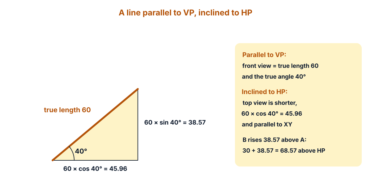
Figure Q6a: the true length 60 at 40° gives a top view length of 45.96 and a rise of 38.57.
Exam answer (10 marks)
Steps of construction:
- XY line: draw the reference line XY.
- Projector of A: draw a thin vertical projector at a convenient place for end A.
- Front view of A: mark a’ on it, 30 mm above XY.
- Top view of A: mark a on the same projector, 35 mm below XY.
- Front view angle: through a’ draw a thin horizontal line and set off 40° above it.
- True length: along the 40° line mark b’, 60 mm from a’. a’b’ is the front view in true length.
- Projector of B: from b’ draw a vertical projector down below XY.
- Top view: through a draw a line parallel to XY. It meets the projector from b’ at b. ab is the top view.
- Check: ab must measure 45.96 mm, and b’ must be 68.57 mm above XY.
- Finish: make a’b’ and ab thick, keep projectors thin, and label a’, b’, a, b, the angle 40° and the distances 30 and 35.
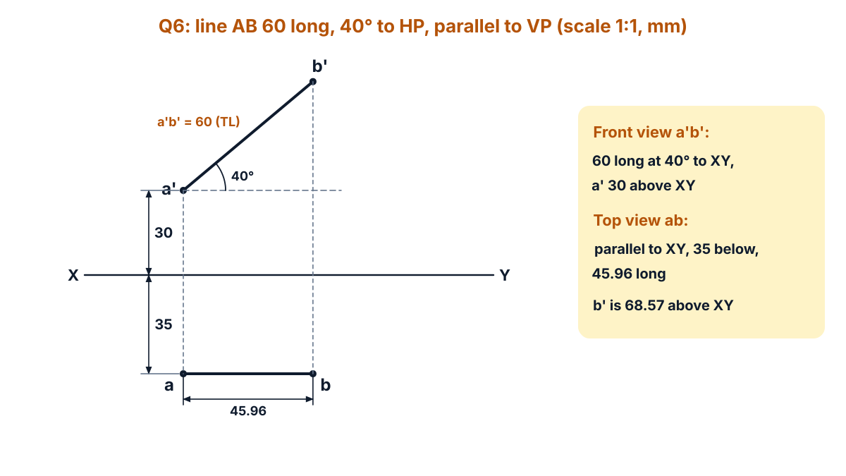
Figure Q6b: front view a’b’ in true length at 40°, top view ab parallel to XY (drawn to scale; draw it full size (scale 1:1) on your sheet, all dimensions in mm).
Answer: front view a’b’ = 60 mm at 40° to XY, with a’ 30 mm and b’ 68.57 mm above XY; top view ab = 45.96 mm, parallel to XY and 35 mm below it.
Q7. A hexagonal pyramid of height 90 mm and base of 40 mm each side. (10 marks)
Question (as printed): 7. A hexagonal pyramid of height 90 mm and base of 40 mm each side. It is resting on VP on its base such that one of its base edge is resting and parallel to HP.
The question prints no instruction. It means: draw its projections.
Understand it first
- A hexagonal pyramid has a regular hexagon as its base and one point at the other end, the apex.
- The axis joins the centre of the base to the apex. Its length is the height, here 90 mm.
- The lines from the apex to the six base corners are the slant edges.
- Resting on VP on its base means the base is flat against the wall. The axis is perpendicular to VP, and the apex points towards you, 90 mm in front of VP.
- So the front view shows the true shape of the hexagon. The top view shows the base as a straight line on XY (it lies in VP) and the apex 90 mm below XY.
- “One base edge resting on HP and parallel to HP” means the bottom edge of the hexagon lies on XY in the front view.
- A hexagon of side 40 is 69.28 mm across the flats (40 × √3) and 80 mm across the corners. So the centre o’ is 34.64 mm above XY.
- From above, the top corners hide the bottom corners exactly below them. So in the top view, f and b fall on one point, and so do e and c. We write the hidden one in brackets: f(b), e(c).
Think of an umbrella-shaped lampshade fixed with its open six-sided end flat on a wall and one edge on the floor. From the front you see the hexagon with lines meeting at the centre. From above you see a triangle.
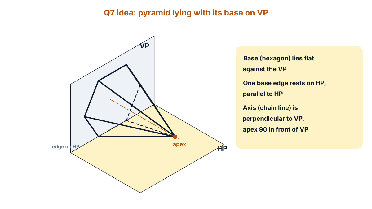
Figure Q7a: the pyramid lies with its base on VP and one base edge on HP; the axis is perpendicular to VP (hidden edges dashed).
The March 2025 paper asked a hexagonal pyramid resting on HP. Here it rests on VP, so the front view and top view swap their roles.
Exam answer (10 marks)
Steps of construction:
- XY line: draw XY.
- Base edge: above XY, draw the edge b’c’, 40 mm long, on XY.
- Hexagon: on b’c’ complete a regular hexagon of side 40 (angles 120°) above XY. Name the corners a’ (left), b’, c’ (bottom), d’ (right), e’ and f’ (top).
- Centre: mark the centre o’, 34.64 mm above XY, where the long diagonals a’d’, b’e’ and c’f’ cross.
- Slant edges in front view: join o’ to all six corners. The apex is nearest to you, so all these lines are visible.
- Projectors: draw vertical projectors down from a’, d’, and from b’ and f’ (one line) and c’ and e’ (one line) to XY, and from o’ below XY.
- Base in top view: the base lies on VP, so its top view is a line on XY from a to d, 80 mm long, with f(b) and e(c) on it.
- Apex: on the projector from o’, mark o, 90 mm below XY.
- Slant edges in top view: join o to a, f(b), e(c) and d. oa and od are the outline; of(b) and oe(c) lie inside.
- Finish: make the outlines thick, keep projectors thin, label every corner, and write the sizes 40 and 90.
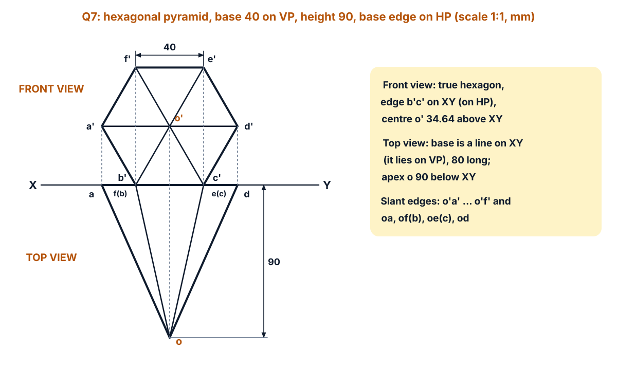
Figure Q7b: front view (true hexagon) and top view (triangle) of the pyramid resting on VP (drawn to scale; draw it full size (scale 1:1) on your sheet, all dimensions in mm).
Answer: front view: a regular hexagon of side 40 with b’c’ on XY and six slant edges meeting at o’, 34.64 mm above XY; top view: a triangle with its base 80 mm long on XY and apex o 90 mm below XY.
Q8. A hexagonal prism, side of base 40 mm and axis 80 mm long, rests at with its base on HP such that one of its rectangular face is parallel to 20 mm infront of VP. (10 marks)
Question (as printed): 8. A hexagonal prism, side of base 40 mm and axis 80 mm long, rests at with its base on HP such that one of its rectangular face is parallel to 20 mm infront of VP. A section plane parallel to VP and perpendicular to HP cuts the solid at 15 mm from the axis. Draw its projections.
“Rests at with” has a stray word, and “parallel to 20 mm infront of VP” means parallel to VP and 20 mm in front of it.
Understand it first
- A hexagonal prism has two hexagon ends and six rectangular side faces. Here the side of the hexagon is 40 mm and the axis is 80 mm long.
- Base on HP means it stands upright. Its top view is a true hexagon, and its front view is made of rectangles 80 mm high.
- “A rectangular face parallel to VP, 20 mm in front” means the back face of the hexagon shows in the top view as a line parallel to XY, 20 mm below it.
- A section plane (cutting plane) is an imaginary knife. This one is parallel to VP and perpendicular to HP. In the top view it shows as a line parallel to XY, called the HT (horizontal trace).
- The plane is 15 mm from the axis. This answer takes it 15 mm in front of the axis, the usual reading, and removes the front part (the part between you and the plane), as the BIS code does for sections.
- The sectional front view shows the part left behind, seen from the front. The cut face is shown with hatching: thin parallel lines at 45°.
- The plane is parallel to VP, so the front view shows the cut face in its true shape (real size). Here it is a rectangle. No auxiliary view is needed.
- The width of the cut face comes from the top view: the HT cuts the two slanting sides 31.34 mm on each side of the axis, so the cut face is 62.68 mm wide and 80 mm high.
Slice a hexagonal pencil along its length, a little in front of the lead, and lift off the front piece. Looking from the front, you see a flat rectangle of wood.
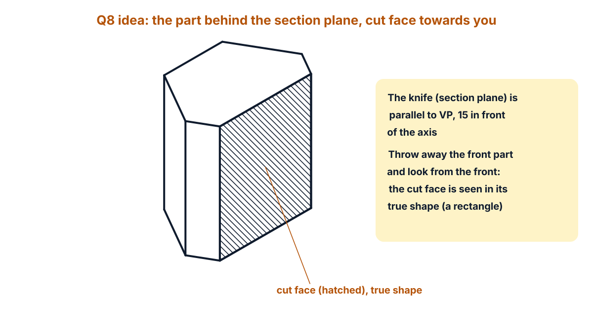
Figure Q8a: after the front part is removed, the cut face faces you and shows in true shape.
Exam answer (10 marks)
Steps of construction:
- XY line: draw XY.
- Top view: below XY draw a regular hexagon of side 40 with its back edge bc parallel to XY and 20 mm below it. The axis o is 54.64 mm below XY.
- Front view: project the corners up and draw the front view of the whole prism: rectangles 80 mm high on XY, 80 mm wide overall.
- Section plane: in the top view draw the HT as a chain line parallel to XY, 15 mm in front of the axis (69.64 mm below XY). Add arrows to show the viewing direction.
- Section points: mark 1 and 2 where the HT cuts the sides af and de. They are 31.34 mm on each side of the axis.
- Removed part: show the part of the top view in front of the HT (corners f and e) with thin lines; the part behind it stays thick.
- Project the section: from 1 and 2 draw projectors up to the front view. They give the vertical edges 1’ and 2’ of the cut face, 80 mm high.
- Sectional front view: draw the retained part thick: outline 80 wide (from a’ to d’) and 80 high, with the cut face 1’2’ in the middle, 62.68 mm wide.
- Hatching: hatch the cut face with thin lines at 45°, about 3 mm apart. Do not draw hidden lines in a sectional view.
- Finish: label SECTIONAL FRONT VIEW, TOP VIEW, HT, a’, d’, 1’, 2’, and write the sizes 20, 15, 80 and 62.68.
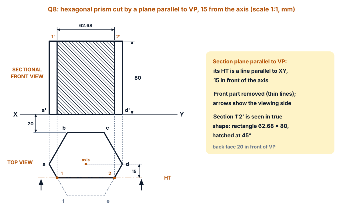
Figure Q8b: top view with the HT and sectional front view with the hatched true shape (drawn to scale; draw it full size (scale 1:1) on your sheet, all dimensions in mm).
Answer: top view: a hexagon of side 40, back edge 20 mm below XY, HT 15 mm in front of the axis; sectional front view: 80 × 80 with the cut face a hatched rectangle 62.68 mm × 80 mm, shown in true shape.
Exam tip: a plane parallel to VP gives the true shape in the front view itself. Do not draw an extra auxiliary view; that is needed only when the plane is inclined.
Q9. A pictorial drawing is given below. Draw its front view, top view and right-side view. (10 marks)
Question (as printed): 9. A pictorial drawing is given below. Draw its front view, top view and right-side view.
[Figure: a pictorial (isometric) view of a stepped block with one arrow X. Printed dimensions: 104 (length), 72 (width), 48 (height), 24 and 24 (step widths), 16 and 16 (step heights) and 24 (end block length).]
Understand it first
- Orthographic projection shows a solid object with flat views, each seen straight on from one side.
- The front view is seen in the direction of the arrow X, here looking at the 104 mm long face. The top view is seen from above. The right side view is seen from the right end.
- In first angle projection the top view goes directly below the front view, and the right side view goes to the left of the front view, at the same height.
- In the top view, the front of the object is at the bottom (farthest from XY). In the right side view, the front of the object is on the left (farthest from the front view).
- Reading this figure: the block is 104 long, 72 wide and 48 high. At the right end is a full-height block, 24 long, across the whole width. On the left 80 mm there are three steps, each 24 deep: 16 high at the front, 32 in the middle and 48 at the back.
- Seen from the right, the end block is a solid wall 72 × 48, with the steps behind it. Edges you cannot see are hidden edges, drawn as dashed lines. So the right side view is a rectangle with the step outline dashed.
Picture a staircase of three steps with a tall wall at its right end. Standing at the right, you see only the wall, but you know the steps are behind it.
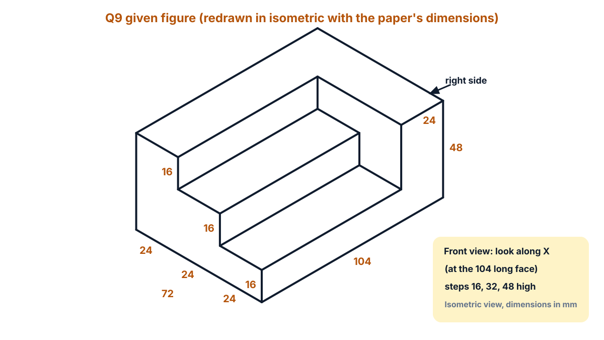
Figure Q9a: given figure (redrawn) from the paper’s dimensions, with the arrow X and the right side direction (isometric view, dimensions in mm).
Exam answer (10 marks)
Steps of construction:
- Layout: draw XY. Leave room for the front view above it, the top view below it and the right side view to the left of the front view.
- Front view outline (X): draw a rectangle 104 wide and 48 high.
- Step lines in front view: draw horizontal lines at 16 and 32 mm height, from the left end to 80 mm.
- End block in front view: draw a vertical line at 80 mm from the left, from 16 up to 48 mm.
- Top view outline: below XY draw a rectangle 104 × 72. Its back edge is nearest XY and its front edge is at the bottom.
- Step lines in top view: draw lines 24 and 48 mm from the front edge, from the left end to 80 mm.
- End block in top view: draw a line at 80 mm from the left, from the front edge to the line 48 from the front.
- Right side view outline: to the left of the front view, at the same height, draw a rectangle 72 wide and 48 high, front on the left and back on the right.
- Hidden steps in side view: draw the step outline with dashed lines: 16 high for the front 24 mm, 32 high for the middle 24 mm, up to 48 at the back.
- Finish: draw thin projectors between the views, add the main dimensions (104, 72, 48, 24, 16), and label FRONT VIEW, TOP VIEW and RIGHT SIDE VIEW.
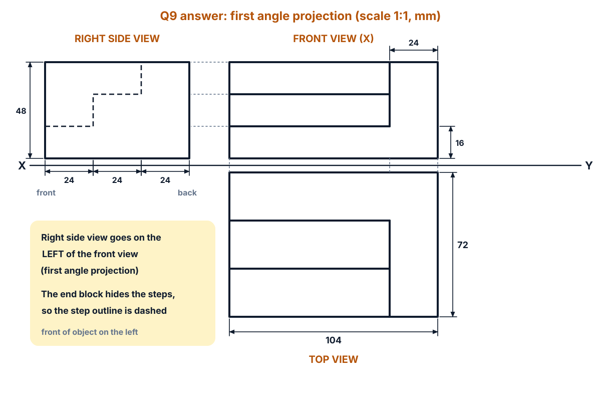
Figure Q9b: front view, top view and right side view in first angle projection (drawn to scale; draw it full size (scale 1:1) on your sheet, all dimensions in mm).
Answer: three views as in Figure Q9b: front view 104 × 48 with two step lines; top view 104 × 72 with two step lines and the end block line; right side view, on the left, 72 × 48 with the step outline dashed.
Exam tip: many students put the right side view on the right. In first angle projection it goes on the left of the front view.
Q10. A pictorial drawing is given below. Draw its front view and top view : (10 marks)
Question (as printed): 10. A pictorial drawing is given below. Draw its front view and top view :
[Figure: a pictorial (isometric) view of a base with two uprights and a rectangular hole, with one arrow X. Printed dimensions: base 56, 32 and 8; height 20 at both uprights; uprights 16 and 8; hole 16 and 12, placed 20 from the left end and 10 from the back edge.]
Understand it first
- The arrow X looks at the 56 mm long face. That gives the front view. The top view is seen from above and goes below XY.
- Reading this figure: a base 56 long, 32 wide and 8 thick.
- Two uprights, each 16 long and 8 wide, stand on the base. Each is 20 high overall, so 12 above the base. The left one is at the back-left corner. The right one is at the front-right corner, flush with the front face.
- A rectangular hole 16 × 12 is cut in the base, 20 from the left end and 10 from the back edge.
- Not printed: the depth of the hole. The paper’s figure draws the hole a little smaller than its printed sizes; scaled the same way, its depth comes out close to the full 8 mm of the base. So this answer takes it as a through hole.
- From the front, the hole is inside the base, behind the front face. So its two side edges are hidden and drawn dashed in the front view.
- From above, everything is visible: the base, both uprights and the hole.
Think of a book-end tray: a flat slab with a small block at each end and a slot cut in the middle for pens.
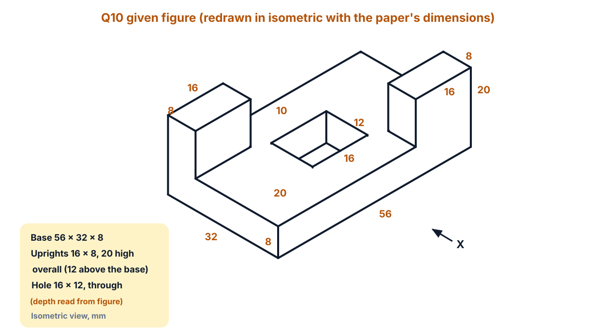
Figure Q10a: given figure (redrawn) from the paper’s dimensions (isometric view, dimensions in mm); the hole depth is read from the figure as through.
Exam answer (10 marks)
Steps of construction:
- Layout: draw XY, with room for the front view above and the top view below.
- Base in front view (X): draw a rectangle 56 wide and 8 high, standing on XY.
- Left upright in front view: on the base, at the left end, draw a rectangle 16 wide reaching 20 mm above XY.
- Right upright in front view: at the right end, draw a rectangle 16 wide reaching 20 mm above XY. Its front face is in line with the base, so no line is drawn between them.
- Hidden hole in front view: draw two dashed vertical lines across the base, 20 and 36 mm from the left end.
- Top view outline: below XY draw the base, a rectangle 56 × 32, back edge nearest XY.
- Left upright in top view: at the back-left corner (next to XY), draw a rectangle 16 × 8.
- Right upright in top view: at the front-right corner (bottom right), draw a rectangle 16 × 8.
- Hole in top view: draw a rectangle 16 × 12, from 20 to 36 mm along the length and 10 mm from the back edge.
- Finish: add thin projectors, the main dimensions (56, 32, 8, 20, 16, 12), and label FRONT VIEW (X) and TOP VIEW.
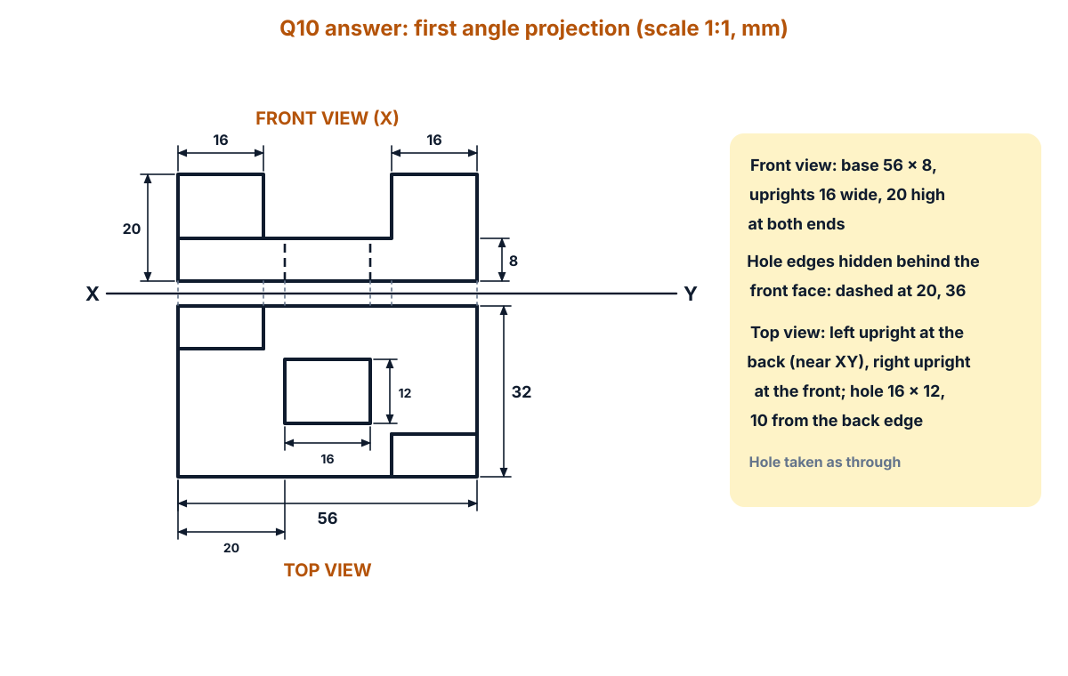
Figure Q10b: front view (X) and top view in first angle projection (drawn to scale; draw it full size (scale 1:1) on your sheet, all dimensions in mm).
Answer: front view: base 56 × 8 with an upright 16 wide and 20 high at each end and two dashed hole lines at 20 and 36; top view: 56 × 32 with the left upright at the back, the right upright at the front and the 16 × 12 hole 10 from the back edge.
FAQ
Which four Part B questions should I choose in the EE-107 October 2025 paper?
Q5 (cycloid), Q6 (line inclined to HP) and Q10 (front and top views only) are the quickest. For the fourth, take Q7 (hexagonal pyramid on VP) if you know solids, or Q9 if you can place a right side view correctly. Q8 (section of a hexagonal prism) is also short once you know that a plane parallel to VP shows the true shape in the front view.
Where does the right side view go in first angle projection?
In first angle projection the right side view goes to the left of the front view, at the same height. The front of the object is on the left side of that view, away from the front view. In Q9 the end block hides the steps, so the step outline in the right side view is drawn with dashed lines.
Q4 shows 2+2 marks but Part A questions carry five marks. What should I write?
The paper prints 2+2, which adds up to 4, while the instructions give five marks to each Part A question. Answer both points fully on one XY line, label every view and write the distances. A neat XY line with clear projectors and labels earns the remaining mark.
Are there misprints in this paper?
Yes. Q6 reads “is inclines” for “is inclined”. Q7 has no instruction; it means draw the projections. Q8 reads “rests at with its base” and “parallel to 20 mm infront of VP”, meaning parallel to and 20 mm in front of VP. Q4 prints a 2+2 split in a five-mark question. None of these changes the drawing.
Which chapters carry the most marks in this Engineering Drawing paper?
Chapter 3 (projections of points, lines, planes and solids) carries 25 marks: Q4, Q6 and Q7. Orthographic projection (Chapter 5) carries 20 marks (Q9, Q10), geometric constructions 15 (Q3, Q5), and Chapters 1 and 4 carry 10 each. These add up to 80, the same as the C-23 weightage.
Sources
- AP SBTET C-23 EE-107 Engineering Drawing question paper, Oct-Nov 2025
- C-23 Curriculum, Diploma in Electrical and Electronics Engineering, SBTET AP
- Reference books (C-23 syllabus):
- P.I. Varghese: Engineering Graphics, McGraw-Hill
- Basant Agarwal & C.M. Agarwal: Engineering Drawing, McGraw-Hill
- N.D. Bhatt: Engineering Drawing
- TTTI Madras: T.S.M. & S.S.M. on Technical Drawing
- SP-46-1998, Bureau of Indian Standards
- SP 46:2003 Engineering Drawing Practice for Schools and Colleges, Bureau of Indian Standards (lettering, dimensioning, sections)
Writes and reviews the SBTET EEE Papers solutions: AP SBTET diploma question papers answered step by step from the prescribed syllabus.