EE-105 Electrical Engineering Material Science Mar-Apr 2026 paper solved: nichrome, hysteresis and eddy current loss and energy stored in a capacitor
 Nookesh Karri ·· 57 min read

This post solves the AP SBTET C-23 DEEE first year electrical engineering material science question paper 2026 (EE-105, March/April 2026 board exam). It answers all 10 Part A questions and all 8 Part B questions. Each question explains the theory in simple words first. Then comes a teacher’s exam answer sized to the marks, with a labelled figure for every question. You can open the original question paper PDF next to this page and check every question word for word.
Electrical Engineering Material Science question paper 2026: pattern and syllabus units
The EE-105 paper of March 2026 follows the C-23 pattern: 3 hours, 80 marks, Part A with 10 questions of 3 marks (30 marks, all compulsory) and Part B with 8 questions of 10 marks, of which you answer any five (50 marks). No sums or circuit figures are printed.
Unlike the October 2025 paper, no Part B question prints a mark split. So this post gives about ten markable points for every 10-mark answer, and five points to each half of a two-part question. The questions match the unit blueprint of the C-23 curriculum exactly: 2, 2, 1, 3 and 2 short questions, and 2, 2, 1, 2 and 1 essay questions from Units 1 to 5.
Part A instructions as printed on the paper (PART—A, 3×10=30):
Instructions : (1) Answer all questions.
(2) Each question carries three marks.
(3) Answers should be brief and straight to the point and shall not exceed five simple sentences.
Part B instructions as printed on the paper (PART—B, 10×5=50):
Instructions : (1) Answer any five questions.
(2) Each question carries ten marks.
(3) Answers should be comprehensive and the criteria for valuation is the content but not the length of the answer.
| Q no | Topic | Syllabus unit | Marks |
|---|---|---|---|
| 1 | Applications of ACSR conductors | Unit 1 Conducting and Semiconducting Materials | 3 |
| 2 | Semiconductor material, with example | Unit 1 | 3 |
| 3 | Classification of insulating materials | Unit 2 Insulating and Dielectric Materials | 3 |
| 4 | Permittivity of air, glass and porcelain | Unit 2 | 3 |
| 5 | Magnetostriction | Unit 3 Magnetic Materials | 3 |
| 6 | Right hand thumb rule | Unit 4 Magnetic Effects of Electric Current and Electromagnetic Induction | 3 |
| 7 | Field pattern of a straight conductor | Unit 4 | 3 |
| 8 | Coefficient of coupling | Unit 4 | 3 |
| 9 | Coulomb’s laws of electrostatics | Unit 5 Electrostatics and Capacitance | 3 |
| 10 | Capacitance and its units | Unit 5 | 3 |
| 11 | Properties and applications of nichrome | Unit 1 | 10 |
| 12 | Intrinsic vs extrinsic semiconductors | Unit 1 | 10 |
| 13 | Properties and applications of PVC | Unit 2 | 10 |
| 14 | Polarization in dielectrics | Unit 2 | 10 |
| 15 | Hysteresis loss and eddy current loss | Unit 3 | 10 |
| 16 | Force on a current carrying conductor | Unit 4 | 10 |
| 17 | Faraday’s laws; effect of an air gap | Unit 4 | 10 |
| 18 | Energy stored in a capacitor | Unit 5 | 10 |
The paper has one misprint: Q7 says “filed patterns” for “field patterns”. The question below copies it exactly, and it does not change what you must draw.
My advice: in Part B, pick Q18, Q16, Q12, Q15 and Q11. Q18 and Q16 are derivations with fixed steps, so every line earns a mark. Q12 is an eight-row table you can learn as a block. Q15 and Q11 are clear lists with one formula or one example each. Skip Q13 unless you know the PVC points by heart. Ten separate points are easy to run short on.
Most Part B topics have come before. Polarization, the force on a conductor and PVC were in the EE-105 paper of October 2024. Intrinsic and extrinsic semiconductors, eddy current loss and Faraday’s laws were in the EE-105 paper of March 2025. The hysteresis loop and the force derivation came again in the EE-105 paper of October 2025. You can see every EE-105 session on the Electrical Engineering Material Science subject page.
Q1. State the applications of ACSR conductors. (3 marks)
Understand it first
- A conductor in a power line is the wire that carries the current from the power station to towns.
- Pure aluminium is light and conducts well. But it is weak. A long span of it sags a lot and can even stretch or snap.
- Steel is very strong, but it conducts poorly.
- ACSR stands for Aluminium Conductor Steel Reinforced. It joins the good points of both metals.
- The centre of the conductor is one or more galvanised steel strands. Galvanised means coated with zinc so that it does not rust. The steel carries the pull (tension).
- Round the steel are layers of aluminium strands. These carry almost all the current.
- Sag is the dip of the wire between two towers. Because steel is strong and stretches less with heat, an ACSR line sags much less than an all-aluminium line.
- So towers can be placed farther apart. Fewer towers means a cheaper line.
Think of a rope with a steel wire inside it. The steel takes the pull and the rope stays straight.
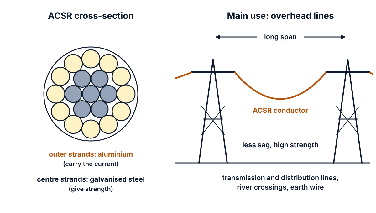
Figure Q1: steel strands at the centre give strength; aluminium strands outside carry the current.
Exam answer (3 marks)
ACSR (Aluminium Conductor Steel Reinforced) has a galvanised steel core surrounded by aluminium strands. Its applications are:
- Overhead transmission lines: it is the most common conductor for high voltage overhead transmission lines, because it is strong, light and cheap.
- Distribution lines and long spans: it is used for overhead distribution lines and for long spans, such as river and valley crossings, where high strength and low sag are needed.
- Other uses: it is used as the earth (ground) wire on transmission towers and for overhead bus bars in outdoor substations.
Key points to write: steel core for strength, aluminium for current; overhead transmission and distribution lines; long spans and river crossings; earth wire.
Q2. Define semiconductor material and give example for it. (3 marks)
Understand it first
- Materials are grouped by how easily they let current flow. Conductors like copper let it flow easily. Insulators like mica hardly let it flow at all.
- A semiconductor sits in between. Its conductivity is lower than a conductor’s but far higher than an insulator’s.
- Silicon (Si) and germanium (Ge) are the common ones. Each atom has four outer electrons, called valence electrons.
- In the band picture, electrons can be in the valence band (tied to atoms) or the conduction band (free to move). The gap between them is the forbidden energy gap, Eg.
- A semiconductor has a small gap. Band gap tables give about 1.1 eV for silicon and 0.7 eV for germanium. (An eV, electron volt, is a tiny unit of energy.)
- Heat gives a few electrons enough energy to jump the gap. So, unlike a metal, a semiconductor conducts better when it is hotter. Its resistance falls with temperature. This is a negative temperature coefficient.
- Adding a tiny amount of impurity (doping) raises its conductivity a lot. That is why diodes and transistors are made from it.
Think of a stream that is dry in winter and flows in summer. A semiconductor “flows” more when heat is given to it.
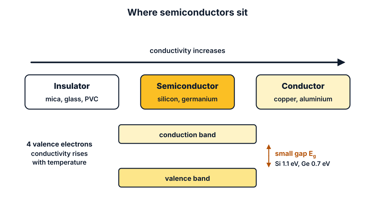
Figure Q2: a semiconductor lies between an insulator and a conductor and has a small energy gap.
Exam answer (3 marks)
- Definition: a semiconductor material is one whose electrical conductivity lies between that of a conductor and an insulator; it has a small forbidden energy gap (about 1 eV).
- Behaviour: its resistance decreases as temperature increases (negative temperature coefficient of resistance), and its conductivity can be increased greatly by adding a small amount of impurity (doping).
- Examples: silicon (Si) and germanium (Ge); compound semiconductors such as gallium arsenide (GaAs) are also used.
Key points to write: conductivity between conductor and insulator; small energy gap; negative temperature coefficient; Si, Ge.
Q3. Classify different types of insulating materials. (3 marks)
Understand it first
- An insulating material is one that does not let current pass through it. It keeps current in its proper path and protects people from shock.
- There are many insulators, so we sort them into groups. Three ways of sorting are common.
- By physical state:
- solid: mica, glass, porcelain, PVC, rubber, paper;
- liquid: transformer oil, varnish;
- gaseous: air, nitrogen, SF6 gas (used in circuit breakers).
- By nature (origin):
- organic: made from living things or carbon compounds, like paper, cotton, wood, rubber and PVC;
- inorganic: made from minerals, like mica, glass, porcelain and asbestos. These stand heat better.
- By temperature (thermal class): heat slowly destroys insulation. So each insulation is given a class. The class is the highest temperature it can safely work at.
- The usual thermal classes are Y (90 °C), A (105 °C), E (120 °C), B (130 °C), F (155 °C) and H (180 °C). Class C covers materials for above 180 °C; newer standards split it into N (200 °C), R (220 °C) and S (240 °C).
A school can sort students by class, by house or by height. Insulators are sorted in the same way, by different features.
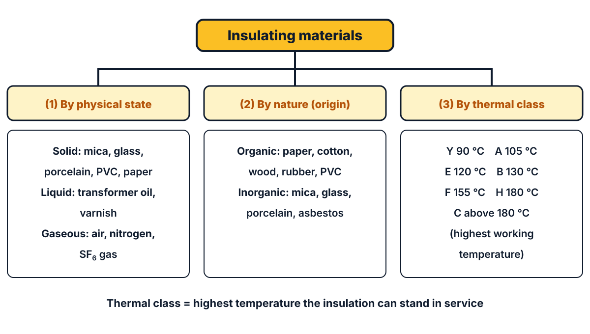
Figure Q3: three ways of classifying insulating materials.
Exam answer (3 marks)
Insulating materials are classified as follows:
- According to physical state: (i) solid: mica, glass, porcelain, PVC, paper, rubber; (ii) liquid: transformer oil, varnishes; (iii) gaseous: air, nitrogen, SF6.
- According to nature: (i) organic: paper, cotton, wood, rubber, PVC; (ii) inorganic: mica, glass, porcelain, asbestos.
- According to temperature (thermal class): Y (90 °C), A (105 °C), E (120 °C), B (130 °C), F (155 °C), H (180 °C) and C (above 180 °C).
Key points to write: solid, liquid, gaseous; organic, inorganic; classes Y, A, E, B, F, H, C with temperatures.
Q4. State the permittivity values for the following di-electric materials : (3 marks)
Question (as printed): 4. State the permittivity values for the following di-electric materials :
(a) Air
(b) Glass
(c) Porcelain
Understand it first
- A dielectric is an insulator placed in an electric field, for example between the plates of a capacitor.
- Permittivity (ε) tells how well a material lets an electric field “pass” and store energy in it. A higher permittivity means a capacitor stores more charge for the same voltage.
- The permittivity of empty space is the absolute permittivity of free space, ε₀ = 8.854 × 10⁻¹² F/m (farad per metre), from the CODATA value.
- Relative permittivity (εr), also called the dielectric constant, compares a material with vacuum: εr = ε / ε₀. It is a ratio, so it has no unit.
- So the absolute permittivity of a material is ε = ε₀ εr, in F/m.
- Books usually give εr. Glass and porcelain are made in many grades, so their values are given as a range.
- Typical values:
- air: about 1. A relative permittivity table gives 1.0006 (1.00058986 at normal temperature and pressure). So air is almost the same as vacuum.
- glass: about 3.7 to 10, depending on the type of glass (the same table lists Pyrex glass at 4.7);
- porcelain: about 5 to 7, from an open table of dielectric constants, which also gives glass as 3.7 to 10.
Worked example (absolute values): air ε = 8.854 × 10⁻¹² × 1.0006 = 8.86 × 10⁻¹² F/m. Glass gives 3.28 × 10⁻¹¹ to 8.85 × 10⁻¹¹ F/m. Porcelain gives 4.43 × 10⁻¹¹ to 6.20 × 10⁻¹¹ F/m.
The question says “permittivity values” without saying relative or absolute. Write the relative values (the usual book form) and add one line on ε = ε₀ εr. Values in books differ a little; any value inside these ranges is correct.
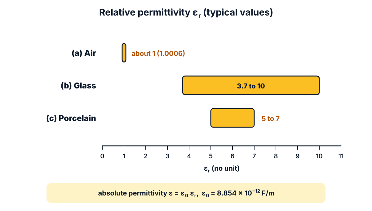
Figure Q4: typical relative permittivity of air, glass and porcelain.
Exam answer (3 marks)
Relative permittivity εr (no unit; absolute permittivity ε = ε₀ εr, with ε₀ = 8.854 × 10⁻¹² F/m):
| Dielectric | Relative permittivity εr |
|---|---|
| (a) Air | about 1 (1.0006) |
| (b) Glass | about 3.7 to 10 (depends on the type of glass) |
| (c) Porcelain | about 5 to 7 |
Key points to write: air ≈ 1; glass 3.7 to 10; porcelain 5 to 7; ε = ε₀ εr.
Q5. Define magnetostriction. (3 marks)
Understand it first
- A ferromagnetic material, like iron or nickel, is made of tiny magnetic regions called domains.
- When the material is magnetised, the domains turn to line up with the field.
- As they turn, the crystal is slightly strained. The piece becomes a little longer or a little shorter.
- This change of size on magnetisation is called magnetostriction. It was first seen in iron by James Joule.
- The change is very small, far too small to see.
- In a transformer, the a.c. flux reverses again and again. The core gets longer and shorter with it, so it vibrates. That vibration is the steady hum you hear from a transformer.
- The rod changes length on both the positive and the negative half of the flux. So the hum is at twice the supply frequency.
- The effect is also put to use, in sonar transducers and some sensors that turn magnetism into tiny movements.
Think of a crowd turning to face the stage. As people turn, the crowd’s shape changes a little. The domains do the same.
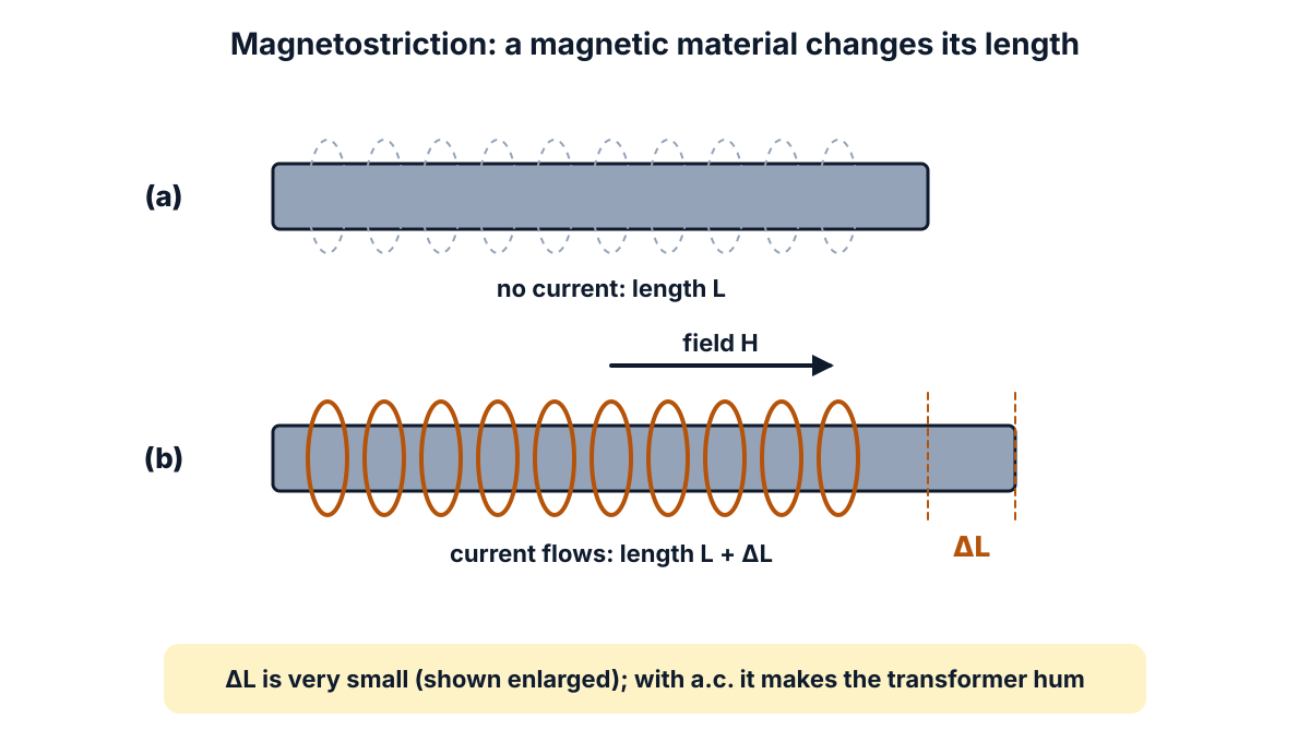
Figure Q5: a magnetised rod changes its length by a tiny amount ΔL (shown enlarged).
Exam answer (3 marks)
- Definition: magnetostriction is the change in the dimensions (length) of a ferromagnetic material when it is magnetised.
- Cause: the domains rotate to line up with the applied field, which strains the crystal; the change in length is very small.
- Effect and use: with alternating flux the core lengthens and shortens repeatedly, producing the humming noise of transformers and chokes; the effect is used in sonar transducers and sensors.
Key points to write: change of dimensions on magnetisation; domain rotation; transformer hum; sonar.
Q6. State right hand thumb rule. (3 marks)
Understand it first
- Every current makes a magnetic field around it. For a straight wire, the lines of force are circles around the wire.
- A circle can go round in two ways: clockwise or anticlockwise. We need a rule to know which.
- The right hand thumb rule gives it. Hold the wire in your right hand, as if gripping a stick.
- Point your thumb along the direction of current.
- Your fingers curl round the wire. The direction of the curl is the direction of the magnetic lines of force.
- For current going upward, the lines go anticlockwise when you look down from above.
- The same rule works for a coil (solenoid). Curl the fingers along the current in the turns, and the thumb points to the north pole.
You can try it with a pen. Hold it in the right hand with the thumb along the pen. Your fingers show the field.
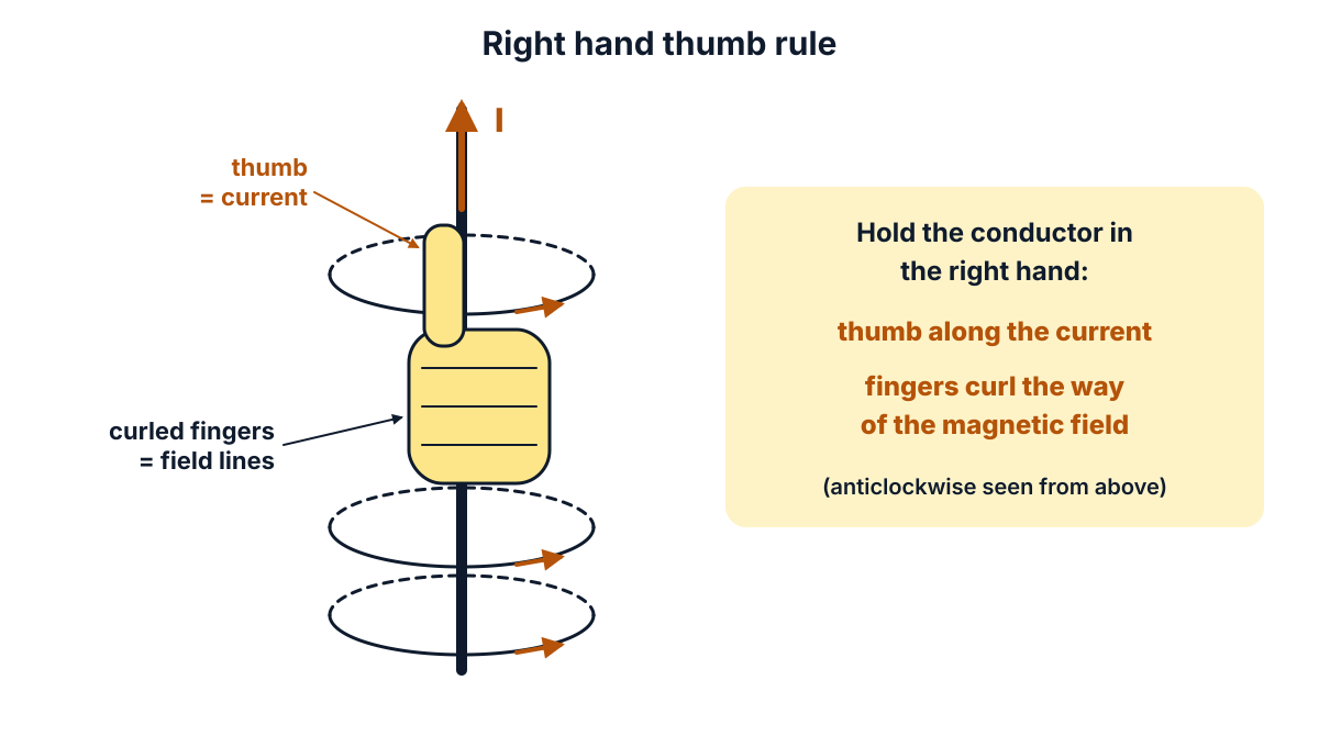
Figure Q6: thumb along the current, curled fingers along the field.
Exam answer (3 marks)
- Statement: if a current carrying conductor is held in the right hand with the thumb stretched along the direction of the current, the curled fingers give the direction of the magnetic lines of force around it.
- Example: for a vertical conductor carrying current upward, the lines of force are anticlockwise when seen from above.
- Use: it finds the direction of the magnetic field of a straight conductor and, with fingers along the current in the turns, the north pole of a solenoid.
Key points to write: right hand grips the conductor; thumb = current; curled fingers = field; also gives the N pole of a coil.
Q7. Draw the filed patterns for straight current carrying conductor. (3 marks)
Understand it first
- “Filed” in the question is a misprint for “field”. Draw the magnetic field pattern of a straight conductor.
- Magnetic lines of force are imaginary lines that show a magnetic field. They are close together where the field is strong.
- Around a long straight current carrying wire, the lines are concentric circles: circles with the wire at their common centre.
- The circles lie in a plane at right angles to the wire.
- The field is strongest near the wire, so the circles are drawn close together there and wider apart farther out.
- When the wire is seen end on:
- a dot (⊙) shows current coming out of the page, towards you;
- a cross (⊗) shows current going into the page, away from you.
- By the right hand thumb rule (Q6), current out of the page gives anticlockwise circles. Current into the page gives clockwise circles.
- You can see this in a lab. Push a wire through a card, pass a large current, sprinkle iron filings on the card and tap it. The filings form rings round the wire.
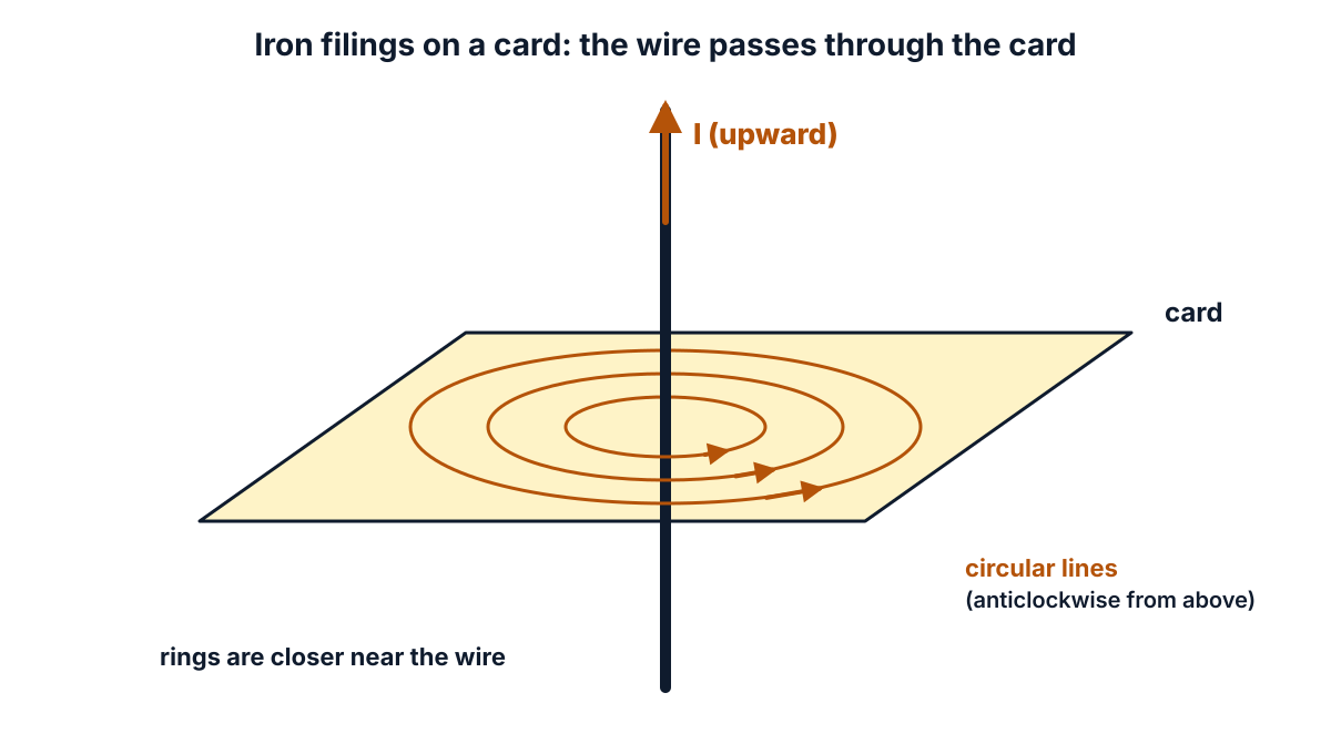
Figure Q7 (i): iron filings on a card form rings round a current carrying wire.
Exam answer (3 marks)
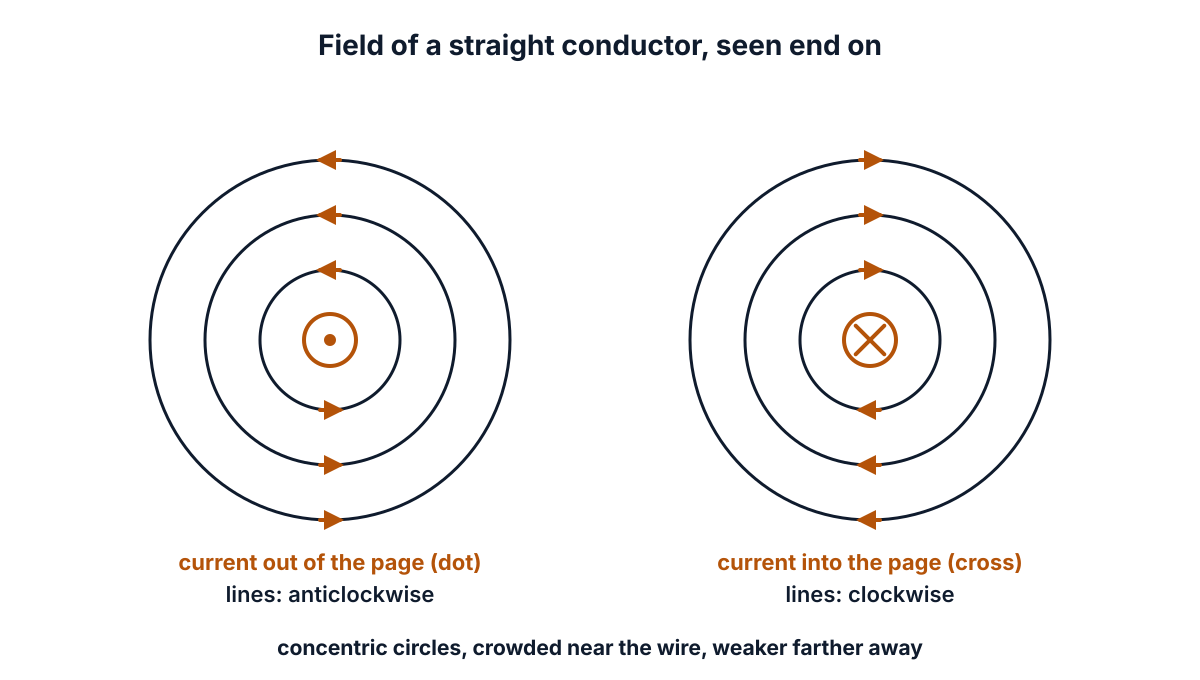
Figure Q7 (ii): field pattern of a straight conductor, for current out of and into the page.
- Pattern: the magnetic lines of force around a straight current carrying conductor are concentric circles in a plane perpendicular to the conductor, with the conductor at the centre.
- Direction: given by the right hand thumb rule; anticlockwise for current out of the page (⊙) and clockwise for current into the page (⊗).
- Strength: the circles are closer near the conductor, where the field is strongest, and spread out with distance.
Key points to write: concentric circles; ⊙ anticlockwise, ⊗ clockwise; right hand thumb rule; closer near the wire.
Q8. Define coefficient of coupling. (3 marks)
Understand it first
- When current flows in a coil, it makes magnetic flux (φ), the total number of magnetic lines.
- Self inductance (L) of a coil measures the emf it induces in itself when its own current changes. Its unit is the henry (H).
- Put a second coil near the first. Some of the flux of coil 1 passes through coil 2 as well. This shared flux is the mutual flux, φ12.
- The rest of the flux of coil 1 does not reach coil 2. It is the leakage flux.
- Mutual inductance (M) measures how much emf a changing current in one coil induces in the other.
- The coefficient of coupling (k) tells what fraction of the flux of one coil links the other: k = φ12 / φ1.
- In terms of inductances, k = M / √(L1 L2).
- k has no unit and always lies between 0 and 1.
- k = 1: all the flux links both coils (tight coupling), nearly true for coils wound on one iron core.
- k = 0: no flux links the other coil (no coupling), as for coils far apart or at right angles.
Worked example: L1 = 0.4 H, L2 = 0.9 H and M = 0.3 H. Then √(0.4 × 0.9) = √0.36 = 0.6, and k = 0.3 / 0.6 = 0.5. Half the flux is shared.
Think of two people sharing an umbrella. If the umbrella covers both fully, k = 1. If only half of the second person is under it, k = 0.5.
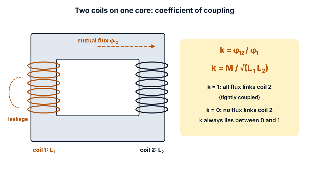
Figure Q8: only the mutual flux φ12 links both coils; k measures this fraction.
Exam answer (3 marks)
- Definition: the coefficient of coupling (k) between two coils is the fraction of the magnetic flux produced by one coil that links the other coil: k = φ12 / φ1.
- Formula: k = M / √(L1 L2), where M is the mutual inductance and L1, L2 are the self inductances of the coils.
- Range: k has no unit and lies between 0 and 1; k = 1 for tightly coupled coils (all flux linked) and k = 0 for magnetically isolated coils.
Key points to write: fraction of flux linking the other coil; k = M / √(L1 L2); 0 ≤ k ≤ 1.
Q9. State Coulomb’s laws of electrostatics. (3 marks)
Understand it first
- Electric charge is a property of matter. It is of two kinds: positive and negative. Its unit is the coulomb (C).
- Charges push or pull each other. This push or pull is the electrostatic force.
- First law: like charges repel each other, and unlike charges attract each other. Two positives push apart; a positive and a negative pull together.
- Second law: the size of the force F between two point charges Q1 and Q2, a distance d apart:
- is directly proportional to the product Q1 Q2;
- is inversely proportional to the square of the distance, d². Double the distance and the force becomes one quarter;
- depends on the medium between them.
- In SI units: F = Q1 Q2 / (4π ε₀ εr d²) newtons.
- Here ε₀ = 8.854 × 10⁻¹² F/m and εr is the relative permittivity of the medium. For air, εr = 1, and 1 / (4π ε₀) is about 9 × 10⁹. So in air F = 9 × 10⁹ × Q1 Q2 / d².
- A medium with a higher εr makes the force weaker by that factor.
Worked example: Q1 = 2 µC and Q2 = 3 µC are 0.3 m apart in air. F = 9 × 10⁹ × 2 × 10⁻⁶ × 3 × 10⁻⁶ / 0.09 = 0.6 N. In a medium of εr = 5, F = 0.6 / 5 = 0.12 N.
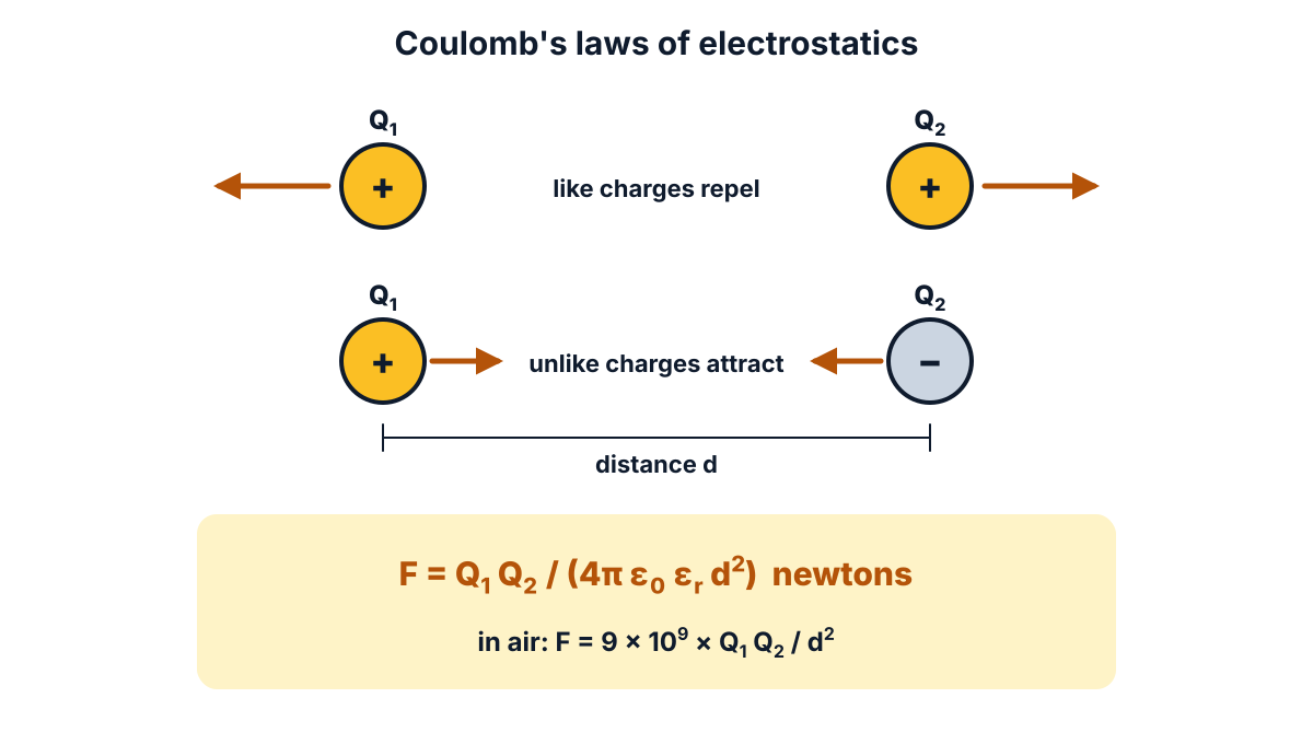
Figure Q9: like charges repel, unlike charges attract, and the force follows the inverse square law.
Exam answer (3 marks)
- First law: like charges repel each other and unlike charges attract each other.
- Second law: the force between two point charges is directly proportional to the product of the charges and inversely proportional to the square of the distance between them, and it depends on the medium.
- Expression: F = Q1 Q2 / (4π ε₀ εr d²) newtons; in air, F = 9 × 10⁹ Q1 Q2 / d² newtons, with Q in coulombs and d in metres.
Key points to write: like repel, unlike attract; F ∝ Q1 Q2 / d²; F = Q1 Q2 / (4π ε₀ εr d²).
Q10. Define capacitance and state its units. (3 marks)
Understand it first
- A capacitor is two conductors (plates) separated by an insulator called the dielectric. It stores electric charge.
- When a voltage V is applied, one plate gets a charge +Q and the other −Q.
- A bigger voltage pushes more charge on. Q rises in proportion to V.
- Capacitance (C) is the charge stored per volt: C = Q / V.
- Its unit is the farad (F). 1 farad = 1 coulomb per volt. A capacitor has 1 F if 1 V stores 1 C on it.
- The farad is a very large unit. So we use smaller units:
- 1 microfarad (µF) = 10⁻⁶ F;
- 1 nanofarad (nF) = 10⁻⁹ F;
- 1 picofarad (pF) = 10⁻¹² F.
- Capacitance depends on the plate area, the gap between the plates and the dielectric. Bigger plates, a smaller gap and a dielectric with higher εr give more capacitance.
Worked example: a capacitor stores 2 mC (0.002 C) at 200 V. C = 0.002 / 200 = 10⁻⁵ F = 10 µF.
A capacitor is like a water tank. Capacitance is how much water it holds for each metre of water pressure.
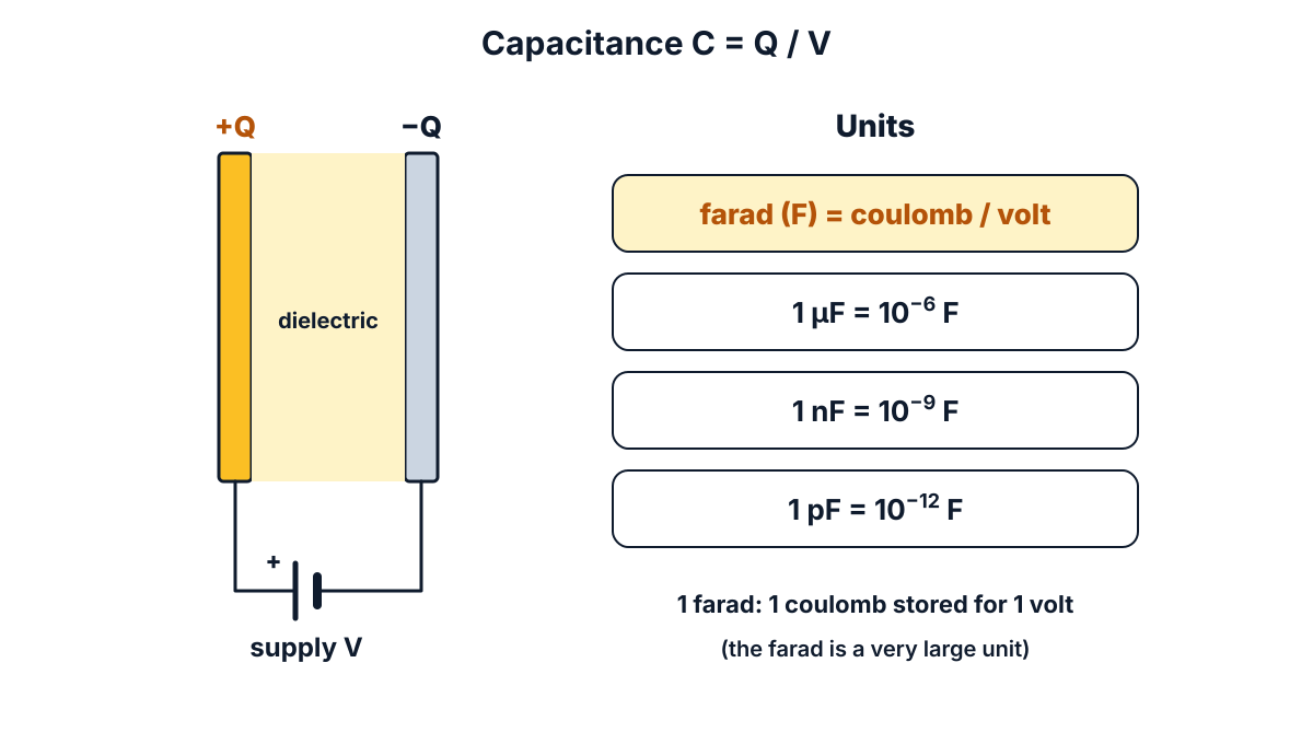
Figure Q10: capacitance is charge per volt; the farad and its smaller units.
Exam answer (3 marks)
- Definition: capacitance is the property of a capacitor to store electric charge; it is the ratio of the charge on either plate to the potential difference between the plates: C = Q / V.
- SI unit: farad (F); a capacitor has a capacitance of 1 farad if a charge of 1 coulomb raises its potential difference by 1 volt (1 F = 1 C/V).
- Practical units: microfarad (1 µF = 10⁻⁶ F), nanofarad (1 nF = 10⁻⁹ F) and picofarad (1 pF = 10⁻¹² F).
Key points to write: C = Q / V; farad = coulomb per volt; µF, nF, pF.
Q11. State the properties and applications of nichrome. (10 marks)
Understand it first
- Most wires should waste as little energy as possible, so they are made of copper or aluminium. These are low resistivity materials.
- A heater does the opposite job. Its wire must turn electric energy into heat. For this we need a high resistivity material.
- Resistivity (ρ) is the resistance of a piece of material 1 m long and 1 m² in cross-section. Its unit is the ohm metre (Ω m).
- Nichrome is an alloy (a mixture of metals) of nickel and chromium. The common grade is about 80% nickel and 20% chromium.
- Its resistivity is about 1.12 µΩ m (1.12 × 10⁻⁶ Ω m). That is about 65 times that of annealed copper, which is 1.72 × 10⁻⁸ Ω m in a standard resistivity table.
- It melts at about 1400 °C, so it can glow red hot without melting.
- When it is heated in air, a thin layer of chromium oxide forms on its surface. This layer stops oxygen reaching the metal, so the wire does not burn away. This is why it lasts for years in a heater.
- Its resistance changes very little with temperature (low temperature coefficient of resistance). So the heater’s power stays steady as it warms up.
- It is ductile: it can be drawn into thin wire or rolled into ribbon, and wound into coils.
Why high resistivity matters, with numbers. Take a nichrome wire 5 m long and 0.5 mm in diameter, so its radius is 0.25 mm:
- Area A = π r² = π × (0.25 × 10⁻³)² = 1.963 × 10⁻⁷ m².
- Resistance R = ρ l / A = 1.12 × 10⁻⁶ × 5 / 1.963 × 10⁻⁷ = 28.52 Ω.
- On a 230 V supply, current I = 230 / 28.52 = 8.06 A, and power P = V² / R = 230² / 28.52 = 1855 W, about 1.85 kW. That is a room heater.
- A copper wire of the same size and length has only 0.438 Ω. To get 28.52 Ω from copper you would need about 326 m of it. Nichrome does it in 5 m.
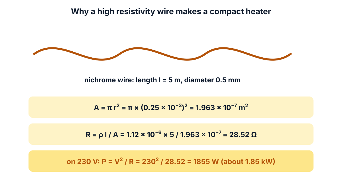
Figure Q11 (i): a short nichrome wire gives the resistance a heater needs.
The C-23 syllabus lists nichrome with tungsten and carbon as the high resistance materials. The paper prints no mark split, so this answer gives 5 marks to properties and 5 to applications.
Exam answer (10 marks)
Nichrome is an alloy of nickel and chromium (about 80% Ni and 20% Cr); it is the most widely used high resistivity material for heating elements.
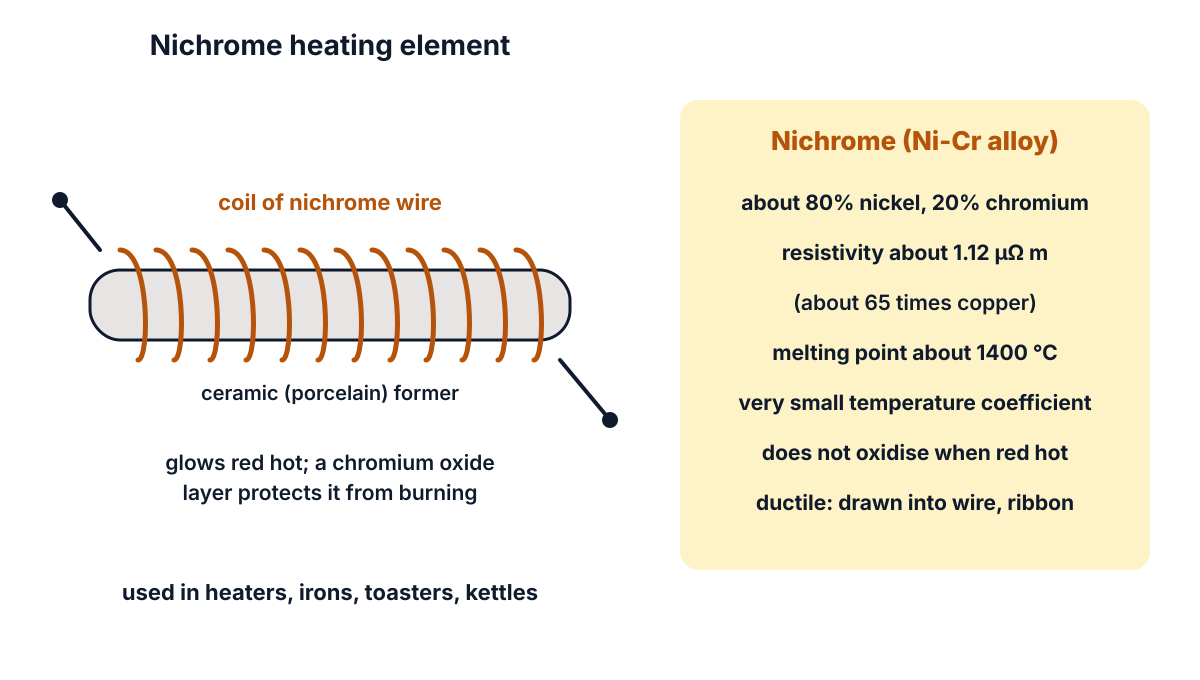
Figure Q11 (ii): a nichrome heating element wound on a ceramic former.
(a) Properties (5 marks)
- High resistivity: about 1.12 × 10⁻⁶ Ω m, about 65 times that of copper, so a short length gives a high resistance.
- High melting point: about 1400 °C, so it can work at red heat.
- Resistance to oxidation: on heating it forms a protective layer of chromium oxide, so it does not oxidise or burn away at high temperature.
- Low temperature coefficient of resistance: its resistance stays nearly constant as it heats up, so the heat output is steady.
- Mechanical properties: it is ductile and strong, so it can be drawn into fine wire or ribbon and wound into coils; it is not affected by most chemicals.
(b) Applications (5 marks)
- Domestic heating appliances: heating elements of room heaters, electric irons, hot plates and electric kettles.
- Toasters and hair dryers: the glowing coils of toasters, hair dryers and heat guns.
- Industrial heating: heating elements of electric furnaces and ovens used for heat treatment and drying.
- Resistors: wire wound resistors and resistance elements of rheostats and starters, where high resistance in a small size is needed.
- Other uses: hot wire foam cutters and igniter wires (fuse wires that glow to ignite a charge).
Conclusion: high resistivity, high melting point and resistance to oxidation make nichrome the standard material for heating elements.
Q12. Distinguish between intrinsic and extrinsic semiconductors in eight aspects. (10 marks)
Question (as printed): 12. Distinguish between intrinsic and extrinsic semiconductors in eight aspects.
Understand it first
- Silicon and germanium have four valence electrons. In a crystal, each atom shares one electron with each of four neighbours. Each shared pair is a covalent bond.
- An intrinsic semiconductor is a perfectly pure crystal. At room temperature, heat breaks a few bonds.
- Each broken bond frees one electron. It also leaves an empty place in the bond, called a hole. A hole acts like a positive charge that can move.
- So in an intrinsic semiconductor, the number of free electrons equals the number of holes. There are only a few of each, so its conductivity is low.
- Doping means adding a very small, controlled amount of another element (the impurity) to the pure crystal.
- A doped crystal is an extrinsic semiconductor. There are two kinds:
- N-type: doped with a pentavalent impurity (5 valence electrons), such as phosphorus, arsenic or antimony. Its fifth electron becomes free. Electrons are the majority carriers.
- P-type: doped with a trivalent impurity (3 valence electrons), such as boron, gallium or indium. One bond is short of an electron, which makes a hole. Holes are the majority carriers.
- Doping adds many carriers, so an extrinsic semiconductor conducts far better than a pure one. Its conductivity is set mainly by the amount of doping, not by temperature.
- In the band picture, doping adds a new energy level inside the gap: a donor level just below the conduction band (N-type), or an acceptor level just above the valence band (P-type).
Think of a quiet class (intrinsic) where only a few students leave their seats. Doping is like adding extra students without seats (N-type) or removing some chairs (P-type). Now many more students move about.
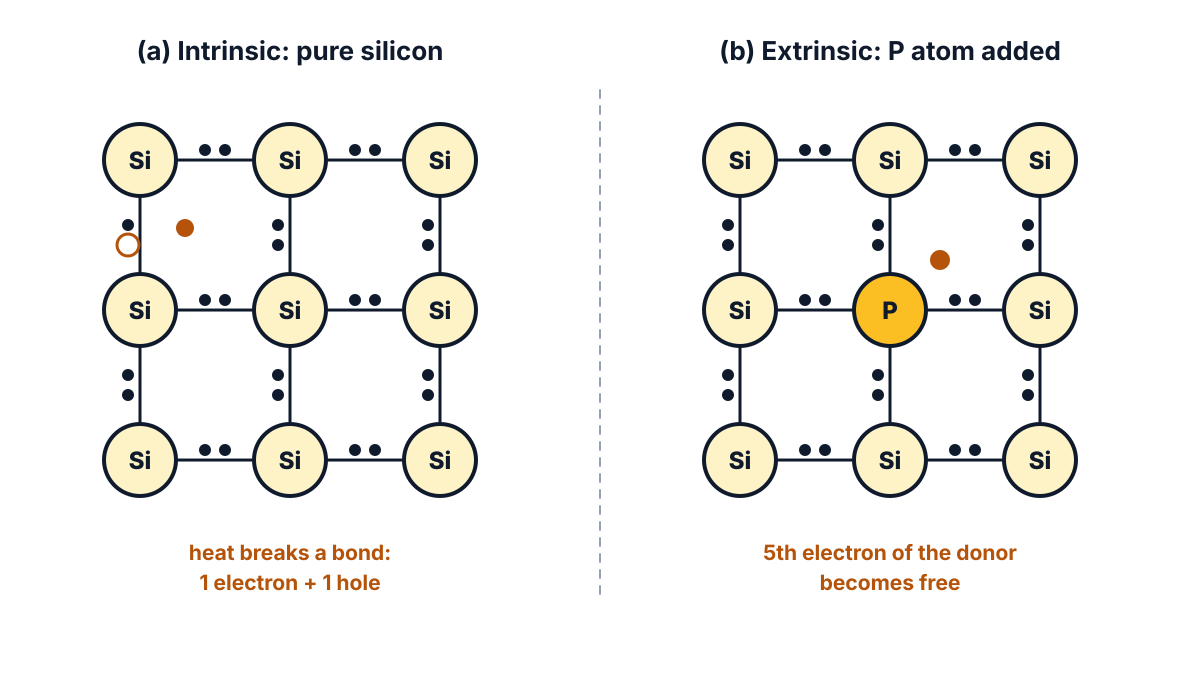
Figure Q12 (i): in pure silicon heat makes electron-hole pairs; in doped silicon the impurity gives extra carriers.
The same comparison, without a fixed number of aspects, came in the March 2025 paper. Here the paper asks for eight aspects for 10 marks. So the answer gives two definition points first, then a table of eight rows: 2 + 8 = 10 markable points.
Exam answer (10 marks)
- Intrinsic semiconductor: a semiconductor in its extremely pure form, such as pure silicon or germanium, in which electrons and holes are produced only by thermal breaking of covalent bonds.
- Extrinsic semiconductor: a semiconductor to which a small, controlled amount of a suitable impurity (pentavalent or trivalent) has been added to increase its conductivity; it is N-type or P-type.
| No | Aspect | Intrinsic semiconductor | Extrinsic semiconductor |
|---|---|---|---|
| 3 | Purity | pure semiconductor | impure (doped) semiconductor |
| 4 | Impurity added | none | pentavalent (P, As, Sb) or trivalent (B, Ga, In) |
| 5 | Number of carriers | free electrons = holes | electrons ≫ holes (N-type) or holes ≫ electrons (P-type) |
| 6 | Conductivity | low | high |
| 7 | Conductivity depends on | temperature only | mainly the amount of doping (and temperature) |
| 8 | Energy levels in the gap | no extra level | donor level near the conduction band or acceptor level near the valence band |
| 9 | Types | only one type | two types: N-type and P-type |
| 10 | Use | not used directly in devices | used to make diodes, transistors and ICs |
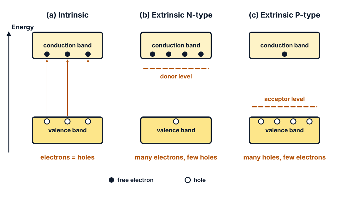
Figure Q12 (ii): band diagrams of an intrinsic, an N-type and a P-type semiconductor.
Conclusion: an intrinsic semiconductor is pure with equal electrons and holes; doping turns it into an extrinsic N-type or P-type semiconductor with much higher, controllable conductivity.
Q13. State the properties and applications of PVC. (10 marks)
Understand it first
- PVC stands for polyvinyl chloride. It is a plastic made by joining many small vinyl chloride molecules into long chains. Such long-chain materials are called polymers.
- PVC is a thermoplastic: it softens when heated and hardens again when cooled. So it can be melted and squeezed round a wire, a process called extrusion.
- Pure PVC resin is hard and stiff. It is mixed with other materials to make cable-grade PVC:
- plasticizer makes it soft and flexible;
- stabilizer stops it breaking down with heat;
- filler adds bulk and lowers the cost;
- additives give colour and better flame resistance.
- About 57% of the mass of PVC is chlorine. The chlorine slows burning, so PVC wires are flame retardant (they do not keep burning on their own).
- It is a good insulator. The same data page gives its dielectric breakdown strength as about 40 MV/m (40 kV/mm).
- It resists water, many chemicals, oil and sunlight, and it is tough.
- Its weak point is heat. It softens at fairly low temperatures. For ordinary PVC the maximum working temperature is around 60 °C, and it starts to break down near 250 °C, giving off harmful fumes.
- Its density is about 1.4 g/cm³, a little heavier than water.
The effects of filler, stabilizer, plasticizer and additives on PVC were asked on their own in the March 2025 paper. Here you need the properties and the uses.
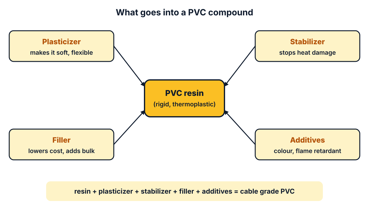
Figure Q13 (i): the ingredients of a PVC compound and what each one does.
Again no split is printed, so give 5 marks to properties and 5 to applications.
Exam answer (10 marks)
PVC (polyvinyl chloride) is a synthetic thermoplastic insulating material made by polymerisation of vinyl chloride; it is mixed with plasticizers, stabilizers, fillers and additives for electrical use.
(a) Properties (5 marks)
- Electrical: it has high insulation resistance and good dielectric strength (about 40 kV/mm), so it is a good insulator at power frequency.
- Flame retardant: because of its high chlorine content it does not support burning; it is self-extinguishing.
- Resistance to environment: it does not absorb much moisture and resists oils, acids, alkalis, sunlight and oxidation.
- Mechanical: it is tough and, with plasticizer, flexible; it can be easily extruded over conductors and coloured for identification.
- Thermal limitation: it is a thermoplastic that softens at low temperature (maximum working temperature around 60 °C for ordinary grades) and gives off harmful fumes when it burns.
(b) Applications (5 marks)
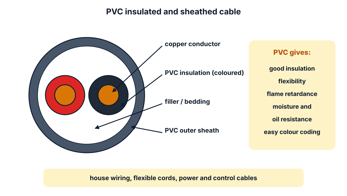
Figure Q13 (ii): a PVC insulated and PVC sheathed cable.
- House wiring: insulation of house wiring cables and flexible cords for appliances.
- Cable sheaths: outer sheath and insulation of low voltage power cables and control cables.
- Conduits and casing: PVC conduit pipes, casing and capping for wiring.
- Insulating accessories: PVC insulating tape, sleeves for joints and terminals.
- Other uses: battery separators, switch and plug parts, and water pipes.
Conclusion: PVC is cheap, flexible, flame retardant and a good insulator, so it is the main insulation for low voltage wires and cables, but it must be kept away from high temperatures.
Q14. Explain polarization in dielectric materials with relevant figures. (10 marks)
Understand it first
- An atom has a small positive nucleus at the centre and a cloud of negative electrons around it. Normally the centre of the cloud sits on the nucleus, so the atom shows no charge from outside.
- An electric dipole is a pair of equal and opposite charges, +q and −q, a small distance d apart. Its strength is the dipole moment, p = q × d, in coulomb metre.
- Put a dielectric between two charged plates. The electric field E pulls the nucleus one way and the electron cloud the other way.
- The two centres separate a little. Each atom becomes a tiny dipole. This is an induced dipole.
- This lining up of charges in a dielectric under an electric field is called polarization. There are three kinds:
- electronic polarization: the electron cloud shifts against the field, the nucleus along it. It happens in every material;
- ionic polarization: in ionic materials like mica and glass, positive ions shift along the field and negative ions against it;
- orientational polarization: some molecules, like water, are dipoles even without a field (polar molecules). They point every way at first. The field turns them to line up.
- Inside the slab, the + end of one dipole sits next to the − end of the next, so they cancel.
- At the two faces they do not cancel. A layer of negative charge appears on the face next to the positive plate, and positive charge on the face next to the negative plate. These are bound charges. They cannot flow away.
- The bound charges make a field opposite to the applied field. So the field inside the dielectric becomes weaker.
- For the same voltage, the plates can now hold more charge. That is why a dielectric increases capacitance, and why εr is greater than 1.
- Polarization P is measured as the dipole moment per unit volume, in C/m².
Picture a row of people holding hands, each leaning right when a wind blows. Inside the row every hand meets a hand. Only the two people at the ends have a free hand. Those free hands are the bound charges.
This topic came, with one sketch, in the October 2024 paper and, with an extra dipole part, in October 2025. Here it asks for “relevant figures” with no split, so the answer gives 6 marks to the explanation and 4 marks to the figures.
Exam answer (10 marks)
(a) Explanation (6 marks)
- Definition: when a dielectric is placed in an electric field, its positive and negative charges are displaced slightly in opposite directions, forming electric dipoles aligned with the field; this is called polarization.
- Electric dipole: each displaced pair of charges +q and −q separated by a distance d forms a dipole of moment p = q d (C m); polarization P is the dipole moment per unit volume (C/m²).
- Electronic polarization: the electron cloud of each atom is displaced against the field relative to the nucleus; it occurs in all dielectrics.
- Ionic polarization: in ionic solids, positive ions are displaced along the field and negative ions against it.
- Orientational polarization: polar molecules, which have permanent dipoles in random directions, rotate to align with the applied field.
- Bound charges and effect: inside the dielectric the dipoles cancel, but a negative bound charge appears on the face near the positive plate and a positive bound charge on the face near the negative plate; their field opposes the applied field, so the net field is reduced and the capacitance increases (εr > 1).
(b) Figures (4 marks)
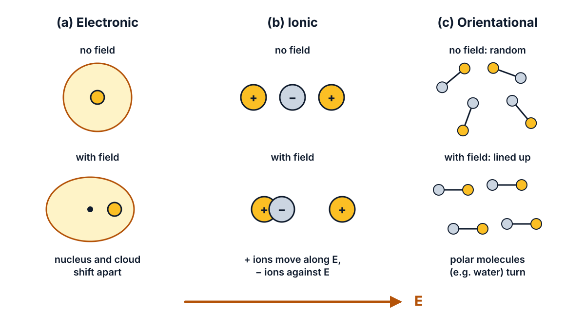
Figure Q14 (i): electronic, ionic and orientational polarization, without and with the field E.
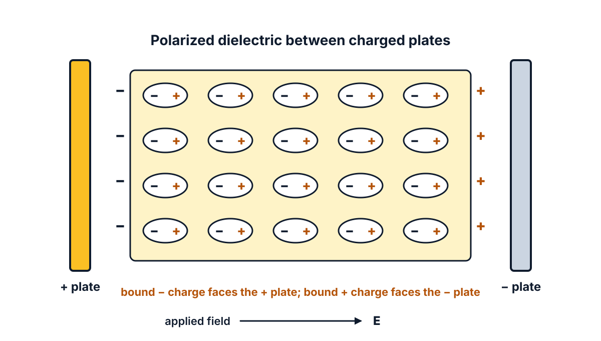
Figure Q14 (ii): a polarized dielectric between charged plates, with bound charges on its faces.
- Atom figure: an atom with no field (cloud centred on the nucleus) and with a field E (nucleus and cloud separated by d).
- Ionic and orientational figures: ions shifted in opposite directions, and polar molecules turned from random directions into line with E.
- Slab figure: a dielectric between a positive and a negative plate, with dipoles lined up along E.
- Labels: mark the field E, the plates and the bound charges on the two faces of the slab.
Conclusion: an electric field turns a dielectric into a set of aligned dipoles; the bound surface charges weaken the field inside, which is why dielectrics increase capacitance.
Q15. Explain hysteresis loss and Eddy current loss. (10 marks)
Understand it first
Both losses happen in the iron core of a transformer or machine when its flux keeps changing. Both turn electric energy into heat. Together they are called iron loss or core loss.
Hysteresis loss
- Magnetising force (H) is the cause, set by the current in the coil. Flux density (B) is the effect, the magnetism the iron actually gets.
- When H is raised, lowered and reversed, B lags behind H. This lag is called hysteresis.
- Plotting B against H over one full cycle gives a closed curve, the hysteresis loop.
- In each cycle the domains of the iron are turned one way, then the other. Turning them takes work, like bending a stiff hinge back and forth. That work becomes heat.
- The energy lost per cycle per unit volume equals the area of the loop.
- Steinmetz found a formula for it: Wh = η Bmax1.6 f V watts. Here η is the Steinmetz hysteresis coefficient (it depends on the material), Bmax the peak flux density, f the frequency and V the volume of iron. The C-23 syllabus asks you to state this equation, not to solve problems on it.
- To reduce it, use a material with a narrow loop, such as silicon steel.
Eddy current loss
- By Faraday’s law, a changing flux induces an emf in any conductor it passes through.
- The iron core is itself a conductor. So emfs are induced inside it too.
- These emfs drive small circulating currents round closed paths inside the core, like whirlpools in water. They are called eddy currents.
- Eddy currents flow through the resistance of the iron and produce heat (I²R). This wasted power is the eddy current loss.
- The usual formula is Pe = Ke Bmax2 f2 t2 V watts, where Ke is a constant and t is the thickness of each lamination.
- Because the loss rises with t², the cure is to make the core from thin sheets called laminations, each coated with varnish. The insulation breaks the big eddy paths into many small ones.
- Adding silicon to the steel raises its resistivity, which also cuts eddy currents.
Think of stirring a big pot of water: one large swirl forms. Put thin plates in the pot, and only tiny swirls are possible. Laminations do this to eddy currents.
The hysteresis loop was asked on its own in the October 2025 paper. The paper prints no split here, so each loss gets 5 marks.
Exam answer (10 marks)
(a) Hysteresis loss (5 marks)
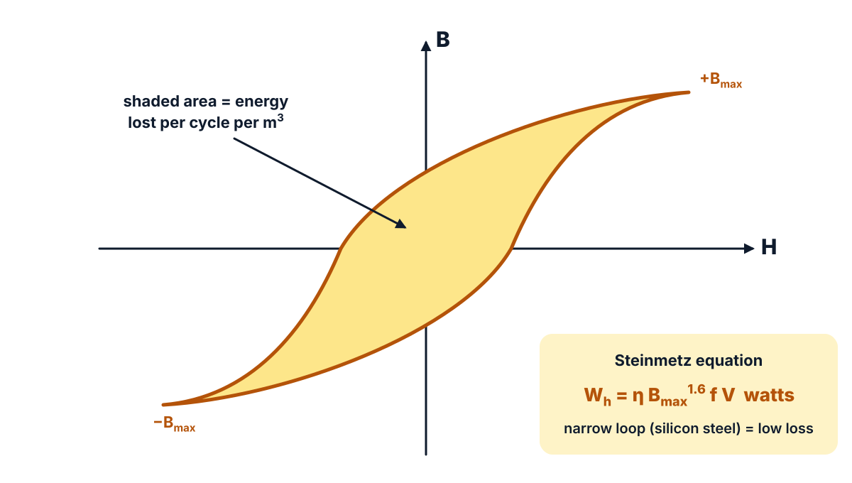
Figure Q15 (i): the area of the hysteresis loop is the energy lost per cycle per unit volume.
- Definition: when a magnetic material is taken through repeated cycles of magnetisation, energy is used up in reversing its domains; this energy appears as heat and is called hysteresis loss.
- Loop area: the energy lost per cycle per unit volume is proportional to the area of the B-H (hysteresis) loop.
- Steinmetz equation: Wh = η Bmax1.6 f V watts, where η = Steinmetz coefficient, Bmax = maximum flux density (T), f = frequency (Hz) and V = volume of the core (m³).
- Factors: it depends on the material (η), the maximum flux density, the frequency and the volume of the core.
- Reduction: use magnetic materials with a narrow hysteresis loop (soft magnetic materials such as silicon steel) for cores of transformers and machines.
(b) Eddy current loss (5 marks)
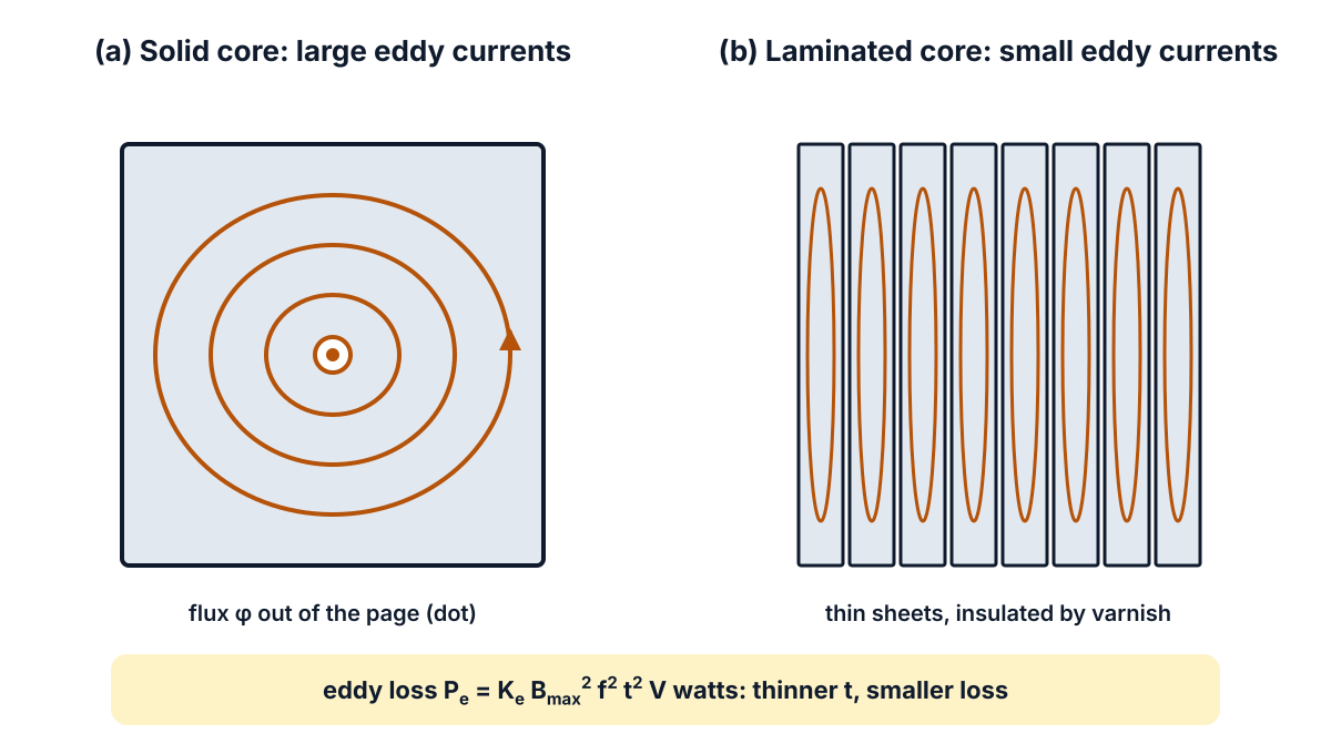
Figure Q15 (ii): a solid core has large eddy currents; thin insulated laminations keep them small.
- Eddy currents: when alternating flux links a magnetic core, emfs are induced in the core itself (Faraday’s law), and these drive circulating currents in the core called eddy currents.
- Loss: the eddy currents flowing through the resistance of the core produce I²R heating; this power loss is called eddy current loss.
- Expression: Pe = Ke Bmax2 f2 t2 V watts, where Ke = eddy current constant and t = thickness of the laminations.
- Reduction by lamination: the core is built from thin laminations insulated from each other by varnish, which breaks up the eddy current paths; the loss falls as the square of the lamination thickness.
- Reduction by material: silicon steel, which has a higher resistivity, is used to reduce the eddy currents further.
Conclusion: hysteresis loss depends on the loop area and is reduced by silicon steel; eddy current loss depends on the square of lamination thickness and is reduced by thin, insulated laminations.
Q16. Derive an expression for force acting on a current carrying conductor placed in a magnetic field. (10 marks)
Question (as printed): 16. Derive an expression for force acting on a current carrying conductor placed in a magnetic field.
Understand it first
- Magnetic flux density (B) tells how strong a field is, in tesla (T). Between two big magnet poles, the field is nearly uniform: straight, parallel, evenly spaced lines from N to S.
- A wire carrying current makes its own circular field around it (Q7).
- Put the wire in the main field. On one side, its circles point the same way as the main field, so the two add and the lines crowd together. On the other side they point opposite ways, so the field is weak.
- Magnetic lines behave like stretched rubber bands. The crowded, bent lines try to straighten, and push the wire from the strong side to the weak side. This push is the mechanical force.
- Fleming’s left hand rule gives its direction. Stretch the thumb, first finger and second finger of the left hand at right angles. First finger along the Field, seCond finger along the Current, thuMb gives the Motion (force).
- Experiments show the force grows with B, with the current I and with the length l of wire inside the field.
- The angle θ between the wire and the field matters too. Split B into two parts:
- B cos θ along the wire. Pushing a pencil along its length does not move it sideways. This part gives no force.
- B sin θ at right angles to the wire. Only this part pushes the wire.
- So F = B I l sin θ newtons. It is largest, F = B I l, when the wire is at right angles to the field (θ = 90°), and zero when the wire lies along the field (θ = 0°).
Worked example: B = 0.8 T, I = 10 A and l = 0.5 m. At θ = 90°, F = 0.8 × 10 × 0.5 = 4 N. At θ = 30°, sin 30° = 0.5, so F = 4 × 0.5 = 2 N.
This force turns every electric motor and moves the pointer of a moving coil meter. With no split printed, the answer below has ten derivation and diagram steps.
Exam answer (10 marks)
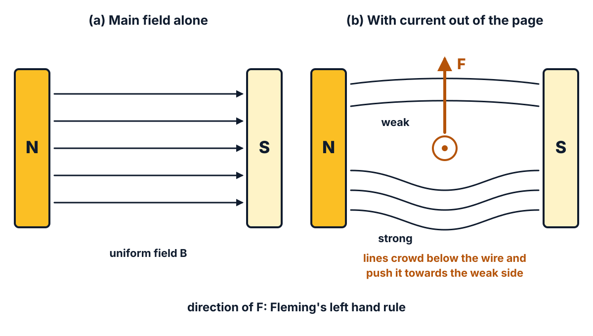
Figure Q16 (i): the main field alone, and the distorted field with current in the conductor.
- Set-up: consider a straight conductor of length l metres carrying a current of I amperes, placed in a uniform magnetic field of flux density B tesla between the poles N and S.
- Field of the conductor: the current sets up concentric circular lines of force around the conductor (right hand thumb rule).
- Resultant field: on one side of the conductor its field is in the same direction as the main field and strengthens it; on the other side it opposes the main field and weakens it.
- Origin of force: the distorted lines of force behave like stretched elastic threads and try to straighten, so they push the conductor from the stronger field side towards the weaker field side; this is the mechanical force F.
- Direction: the force acts at right angles to both the conductor and the field, and its direction is given by Fleming’s left hand rule.
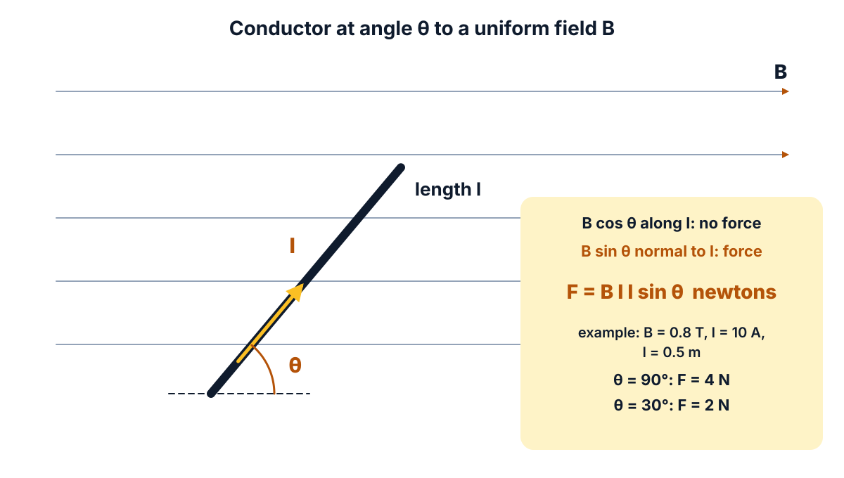
Figure Q16 (ii): only the component B sin θ, at right angles to the conductor, produces the force.
- Angle: let the conductor make an angle θ with the direction of the field; B is resolved into B cos θ along the conductor and B sin θ perpendicular to it.
- Effective component: B cos θ is parallel to the current and produces no force; only B sin θ produces force.
- Proportionality: experiments show that F ∝ B sin θ, F ∝ I and F ∝ l, so F ∝ B I l sin θ, i.e. F = k B I l sin θ.
- Result: in SI units the constant k = 1, so F = B I l sin θ newtons.
- Special cases: when θ = 90° (conductor perpendicular to the field), F = B I l (maximum); when θ = 0° (conductor parallel to the field), F = 0. For example, B = 0.8 T, I = 10 A and l = 0.5 m give F = 4 N at 90°.
Answer: F = B I l sin θ newtons; maximum F = B I l at θ = 90°, zero at θ = 0°; direction by Fleming’s left hand rule.
Q17. (a) State Faraday’s laws of electromagnetic induction. (10 marks)
Question (as printed): 17. (a) State Faraday’s laws of electromagnetic induction.
(b) Explain the effect of air gap in a magnetic circuit.
Understand it first
(a) Faraday’s laws
- Magnetic flux (φ) is the number of magnetic lines through a coil, in webers (Wb). Flux linkage is the flux multiplied by the number of turns N, written N φ.
- Faraday found that a steady flux does nothing. But when the flux through a coil changes, an emf appears in the coil. This is electromagnetic induction.
- The flux can change because a magnet moves, the coil moves, or the current in a nearby coil changes.
- First law: whenever the flux linked with a coil changes, an emf is induced in it. If the circuit is closed, a current flows.
- Second law: the size of the induced emf equals the rate of change of flux linkages: e = N dφ/dt volts.
- A faster change gives a bigger emf. That is why a magnet pushed in quickly makes the meter kick more.
- The direction of the emf is such that it opposes the change that causes it. This is Lenz’s law, so the full form is often written e = −N dφ/dt.
Worked example: a coil of 500 turns has its flux changed by 0.004 Wb in 0.1 s. e = 500 × 0.004 / 0.1 = 20 V.
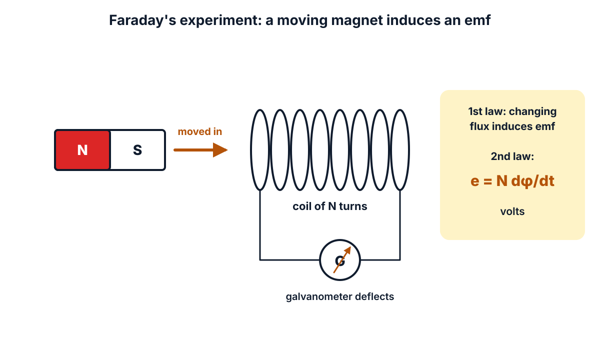
Figure Q17 (i): moving a magnet into a coil changes the flux and induces an emf.
(b) Effect of an air gap
- A magnetic circuit is the closed path followed by magnetic flux, usually an iron core with a coil on it.
- The coil supplies the push, called magnetomotive force (mmf), equal to N I ampere-turns (AT).
- The opposition to flux is the reluctance (S), like resistance in an electric circuit. Flux = mmf / reluctance.
- Reluctance S = l / (μ₀ μr A), where l is the length of the path, A its area, μ₀ = 4π × 10⁻⁷ H/m the permeability of free space and μr the relative permeability.
- Iron has a very large μr (hundreds or thousands). Air has μr = 1. So even a very short air gap has a large reluctance.
- Gaps are often needed: between the stator and rotor of a motor, or at the joints of a core.
- At the gap, the flux spreads out sideways. This bulging is called fringing. More flux also leaks away from the main path (leakage flux).
Worked example: a core of area 10⁻³ m² has an iron path 0.5 m long with μr = 1000. Its reluctance is 0.5 / (4π × 10⁻⁷ × 1000 × 10⁻³) = 3.98 × 10⁵ AT/Wb. Cut a gap of 1 mm: the gap alone adds 0.001 / (4π × 10⁻⁷ × 10⁻³) = 7.96 × 10⁵ AT/Wb. The total becomes 11.94 × 10⁵ AT/Wb, three times the iron alone.
So a gap 500 times shorter than the iron path has twice its reluctance. For the same mmf, the flux falls to one third. To keep the same flux, you need three times the ampere-turns.
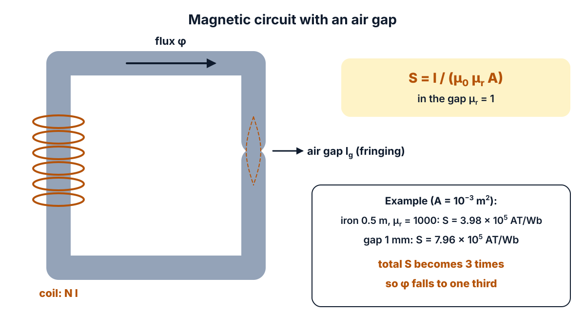
Figure Q17 (ii): a 1 mm air gap in series with the iron path triples the reluctance in this example.
The paper prints no split for Q17, so this answer assumes 5 marks for (a) and 5 marks for (b). Faraday’s laws were a 3-mark question in the October 2024 and March 2025 papers.
Exam answer (10 marks)
(a) Faraday’s laws of electromagnetic induction (5 marks)
- First law: whenever the magnetic flux linked with a conductor or coil changes, an emf is induced in it.
- Current: if the circuit is closed, the induced emf drives an induced current through it.
- Second law: the magnitude of the induced emf is directly proportional to (equal to) the rate of change of flux linkages.
- Expression: e = N dφ/dt volts, where N is the number of turns and dφ/dt the rate of change of flux in Wb/s; with Lenz’s law, e = −N dφ/dt (the emf opposes the change of flux).
- Example: a coil of 500 turns whose flux changes by 0.004 Wb in 0.1 s has an induced emf e = 500 × 0.004 / 0.1 = 20 V.
(b) Effect of air gap in a magnetic circuit (5 marks)
- Increase in reluctance: reluctance S = l / (μ₀ μr A); since μr = 1 for air and is very large for iron, even a short air gap greatly increases the total reluctance of the magnetic circuit.
- More mmf needed: for the same flux, a much larger mmf (ampere-turns) is needed; most of the ampere-turns of the coil are used up across the air gap.
- Fringing: the flux spreads out at the gap (fringing), so the effective area of the gap is larger and the flux density in the gap is less uniform.
- Leakage: the higher reluctance increases the leakage flux, so a larger part of the flux does not follow the useful path.
- Practical effect: the air gap between the stator and rotor of machines is kept as small as possible; in chokes a small air gap is deliberately used to keep the core from saturating.
Answer: e = N dφ/dt; an air gap greatly increases reluctance, so more ampere-turns are needed for the same flux, with fringing and more leakage.
Q18. Derive an expression for energy stored in capacitor. (10 marks)
Understand it first
- A capacitor of capacitance C is connected to a supply of V volts through a switch. At first it has no charge.
- When the switch is closed, charge flows onto the plates. The capacitor voltage v rises from 0 to V.
- At any moment, if the charge on it is q, its voltage is v = q / C.
- To push a tiny extra charge dq onto the plates, the supply must do work against this voltage. Voltage is work per unit charge, so the work is dW = v dq.
- At the start, v is zero, so the first charge goes on free. As the capacitor fills, each new bit of charge costs more work.
- Adding up all the small bits from q = 0 to q = Q gives the total work. This work is not lost. It is stored as energy in the electric field between the plates.
- On a graph of v against q, the line is straight (v = q / C). The energy is the area of the triangle under it: ½ × base × height = ½ × Q × V.
- Using Q = C V, the energy can be written in three ways: W = ½ C V² = ½ Q V = Q² / (2C) joules.
Worked example: C = 10 µF charged to V = 200 V. W = ½ × 10 × 10⁻⁶ × 200² = 0.2 J. Check: Q = C V = 10 × 10⁻⁶ × 200 = 2 × 10⁻³ C, and ½ Q V = ½ × 0.002 × 200 = 0.2 J. The two forms agree.
It is like filling a water tank from the bottom with a pump. The first litres go in easily. As the level rises, each new litre must be lifted higher, so it costs more work.
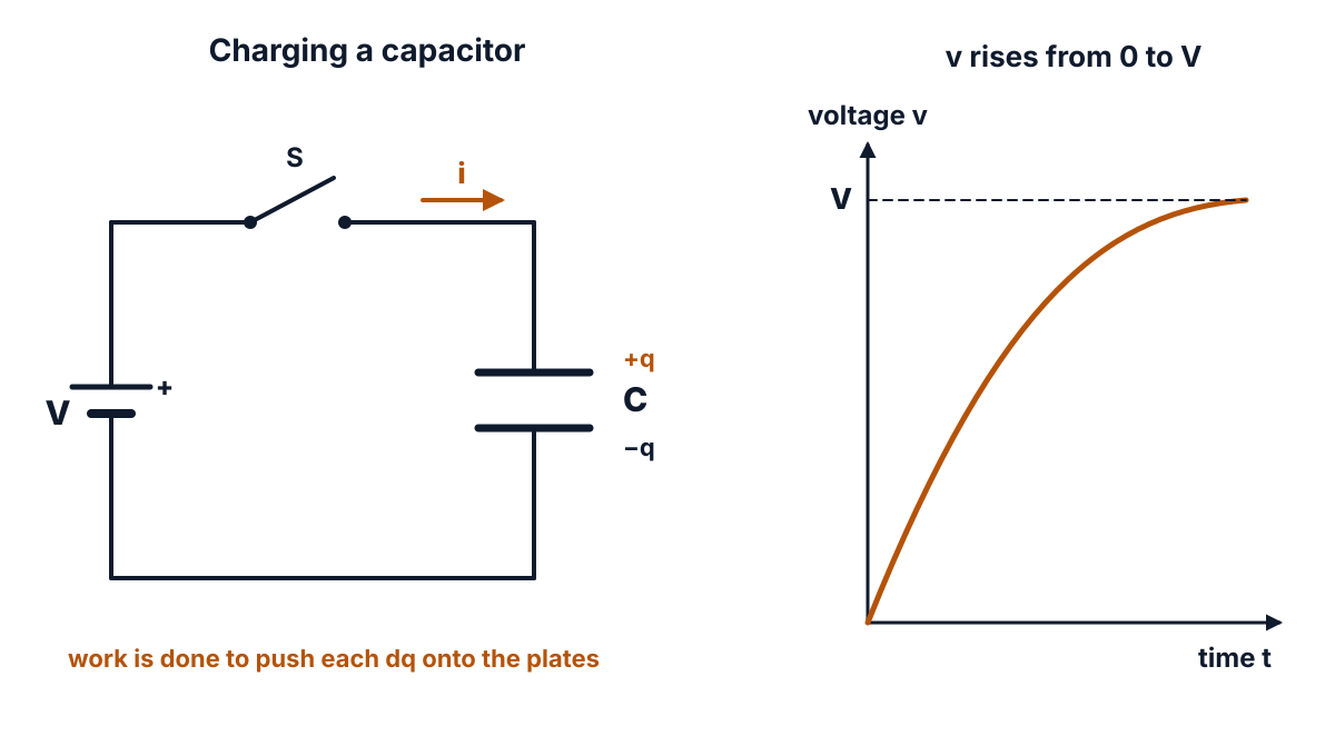
Figure Q18 (i): the capacitor voltage rises from 0 to V as charge flows in.
The paper prints no split, so the answer gives ten derivation and diagram steps.
Exam answer (10 marks)
- Set-up: consider a capacitor of capacitance C farads connected to a d.c. supply of V volts through a switch S; initially it is uncharged.
- Charging: when S is closed, charge flows onto the plates and the potential difference across the capacitor rises from 0 to V as the charge rises from 0 to Q.
- Instantaneous voltage: at any instant, when the charge on the plates is q coulombs, the potential difference is v = q / C volts.
- Work for a small charge: the work done in moving a further small charge dq against this potential difference is dW = v dq = (q / C) dq joules.
- Total work: the total work done in charging from 0 to Q is W = ∫₀Q (q / C) dq.
- Integration: W = (1/C) [q²/2]₀Q = Q² / (2C) joules.
- Other forms: substituting Q = C V gives W = ½ C V² = ½ Q V joules.
- Stored energy: this work is stored as energy in the electric field between the plates, and it is given back when the capacitor discharges.
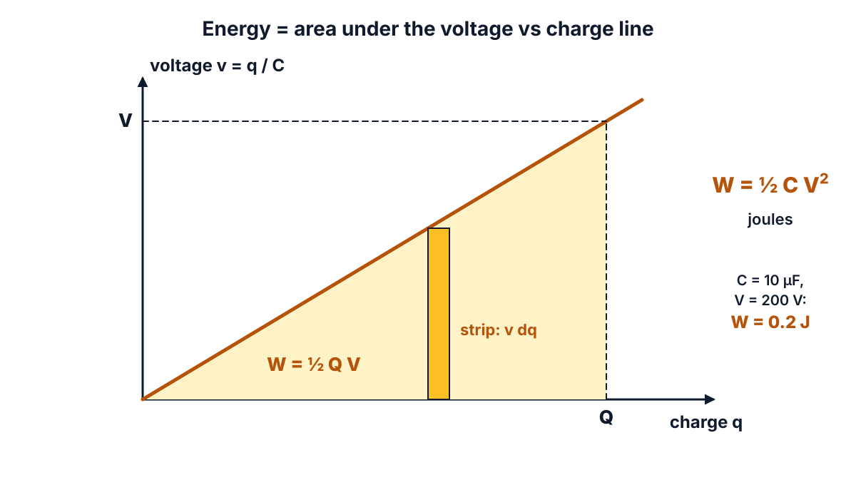
Figure Q18 (ii): the energy stored is the area of the triangle under the v-q line: ½ × Q × V.
- Graphical proof: the graph of v against q is a straight line through the origin; the energy is the area of the triangle under it, ½ × Q × V = ½ C V².
- Example: a 10 µF capacitor charged to 200 V stores W = ½ × 10 × 10⁻⁶ × 200² = 0.2 J.
Answer: W = ½ C V² = ½ Q V = Q² / (2C) joules, stored in the electric field of the capacitor.
FAQ
Which units carry the most marks in the EE-105 March 2026 paper?
Unit 4 (magnetic effects of electric current and electromagnetic induction) carries 29 marks: Q6, Q7, Q8, Q16 and Q17. Units 1 and 2 carry 26 marks each, Unit 5 carries 16 and Unit 3 carries 13. These totals include the Part B choice, so they add up to 110, the unit weightage of the C-23 syllabus.
Which five Part B questions should I choose in this paper?
Q18, Q16, Q12, Q15 and Q11 are the safest five. Q18 and Q16 are standard derivations with fixed steps, Q12 is an eight-row table, and Q15 and Q11 are lists of properties with one formula each. Take Q14 or Q17 only if you can draw their figures well, and Q13 only if you know the PVC points by heart.
The Part B questions print no mark split. How should I divide my answer?
When the paper prints no split, write about ten markable points for each 10-mark question. For a two-part question like Q15 (hysteresis loss and eddy current loss) or Q17 (a) and (b), give five points to each part. For “properties and applications” questions, write five properties and five applications.
Is there a misprint in this paper?
Yes. Q7 prints “filed patterns” for “field patterns”. It does not change the question: draw the magnetic field pattern of a straight current carrying conductor. Q4 also writes “di-electric” with a hyphen, which is only a spelling style.
What permittivity values should I write for air, glass and porcelain in Q4?
Write relative permittivity, which has no unit: air about 1 (1.0006), glass about 3.7 to 10 and porcelain about 5 to 7, as open tables give them. Values differ with the grade of glass and porcelain, so write a range. Add that absolute permittivity is ε₀ εr, with ε₀ = 8.854 × 10⁻¹² F/m.
Sources
- AP SBTET C-23 DEEE EE-105 question paper, Mar-Apr 2026
- C-23 Curriculum, Diploma in Electrical and Electronics Engineering, SBTET AP
- Reference books (C-23 syllabus):
- K. Padmanabham: Electronic Components, Laxmi Publications
- Electrical Engineering Materials, NITTTR Publications
- B.K. Agarwal: Introduction to Engineering Materials, Tata McGraw Hill
- Ian P. Jones: Material Science for Electrical and Electronic Engineers, Oxford
- B.L. Theraja: Electrical Technology Vol. 1, S. Chand
- Aluminium-conductor steel-reinforced cable: construction and sag (Wikipedia)
- Band gap: values for silicon and germanium (Wikipedia)
- Insulation system: thermal classes (Wikipedia)
- Relative permittivity: table of values (Wikipedia)
- Relative permittivity (dielectric constant) of common materials (The Engineering ToolBox)
- Vacuum electric permittivity, CODATA recommended value (NIST)
- Vacuum magnetic permeability, CODATA recommended value (NIST)
- Magnetostriction (Wikipedia)
- Nichrome: composition and properties (Wikipedia)
- Electrical resistivity and conductivity: resistivity table at 20 °C (Wikipedia)
- Polyvinyl chloride: properties and uses (Wikipedia)
Writes and reviews the SBTET EEE Papers solutions: AP SBTET diploma question papers answered step by step from the prescribed syllabus.