EE-105 Electrical Engineering Material Science Mar-Apr 2025 paper solved: hysteresis loop, intrinsic and extrinsic semiconductors and induced EMF
 Nookesh Karri ·· 48 min read

This post solves the AP SBTET C-23 DEEE first year electrical engineering material science question paper of 2025 (EE-105, March/April 2025 board exam). It answers all 10 Part A questions and all 8 Part B questions. Each question first explains the theory in simple words, then gives a teacher’s exam answer sized to the marks, with a labelled figure wherever the textbook answer has one. You can open the original question paper PDF next to this page and check every question word for word.
Electrical Engineering Material Science question paper 2025: pattern and syllabus units
The EE-105 paper of March 2025 follows the C-23 pattern: 3 hours, 80 marks, Part A with 10 questions of 3 marks (30 marks, all compulsory) and Part B with 8 questions of 10 marks, of which you answer any five (50 marks). No sums or figures are printed; Q17 and Q18 are split 5 + 5. The questions match the unit blueprint of the C-23 curriculum exactly: 2, 2, 1, 3 and 2 short questions, and 2, 2, 1, 2 and 1 essay questions from Units 1 to 5.
Part A instructions as printed on the paper (PART—A, 3×10=30):
Instructions : (1) Answer all questions.
(2) Each question carries three marks.
(3) Answers should be brief and straight to the point and shall not exceed five simple sentences.
Part B instructions as printed on the paper (PART—B, 10×5=50):
Instructions : (1) Answer any five questions.
(2) Each question carries ten marks.
(3) Answers should be comprehensive and the criteria for valuation is the content but not the length of the answer.
| Q no | Topic | Syllabus unit | Marks |
|---|---|---|---|
| 1 | Requirements of high resistivity materials | Unit 1 Conducting and Semiconducting Materials | 3 |
| 2 | Hardening and annealing | Unit 1 | 3 |
| 3 | Conductors, insulators and semiconductors | Unit 2 Insulating and Dielectric Materials | 3 |
| 4 | Applications of dielectric materials | Unit 2 | 3 |
| 5 | Eddy current loss | Unit 3 Magnetic Materials | 3 |
| 6 | Faraday’s laws of electromagnetic induction | Unit 4 Magnetic Effects of Electric Current and Electromagnetic Induction | 3 |
| 7 | Field patterns of a straight conductor and a solenoid | Unit 4 | 3 |
| 8 | Lenz’s law | Unit 4 | 3 |
| 9 | Coulomb’s laws of electrostatics | Unit 5 Electrostatics and Capacitance | 3 |
| 10 | Electric flux and flux density | Unit 5 | 3 |
| 11 | Copper and aluminium | Unit 1 | 10 |
| 12 | Intrinsic vs extrinsic semiconductors | Unit 1 | 10 |
| 13 | Filler, stabilizer, plasticizer and additives in PVC | Unit 2 | 10 |
| 14 | Impregnated paper and glass | Unit 2 | 10 |
| 15 | Hysteresis loop | Unit 3 | 10 |
| 16 | Dynamically and statically induced emf | Unit 4 | 10 |
| 17 | (a) Energy stored in a magnetic field (b) Magnetic vs electric circuit | Unit 4 | 5 + 5 |
| 18 | (a) Capacitors in parallel (b) Types of capacitors | Unit 5 | 5 + 5 |
My advice: in Part B, pick Q15, Q16, Q12, Q17 and Q18. The hysteresis loop and the two kinds of induced emf have standard figures and fixed steps, so every point you write can earn a mark. Q17 and Q18 come in two short halves, which is easier than one long essay. Skip Q11, Q13 and Q14 unless you have learnt them by heart: they look easy, but they are pure memory lists.
Several of these topics also came in the EE-105 paper of October 2024, so solve both papers together. You can see every EE-105 session on the Electrical Engineering Material Science subject page.
Q1. State any six requirements of high resistivity materials. (3 marks)
Understand it first
- Resistivity (ρ, rho) is how strongly a material opposes current, for a piece of standard size (1 m long, 1 m² cross-section). Its unit is ohm metre (Ω m).
- High resistivity materials are materials that oppose current strongly. Examples: nichrome, manganin, constantan, tungsten and carbon.
- We use them on purpose where we want resistance or heat: heater elements, lamp filaments, resistors, rheostats and meter shunts.
- The temperature coefficient of resistance tells how much the resistance changes for each degree of temperature change. The idea was asked in the EE-106 paper of October 2025.
Think of a heater coil. It must get red hot every day for years. So it must oppose current (to make heat), not melt, not rust in hot air, and not change its value. Each of these needs is one “requirement”.
Six points for 3 marks means half a mark each. A seventh point earns nothing.
Exam answer (3 marks)
Six requirements, half a mark each:
- High resistivity: so that a short length of wire gives the required resistance.
- Low temperature coefficient of resistance: so that the resistance stays almost constant when the material gets hot.
- High melting point: so that it can work at high temperature, as in heaters and filaments.
- High resistance to oxidation and corrosion: it must not rust or burn away in hot air.
- Good mechanical strength and ductility: it must be strong and easy to draw into thin wire or tape.
- Low thermal emf against copper and good stability: its value must not drift with time, and it must not create unwanted voltages at joints.
Key points to write: high resistivity; low temperature coefficient; high melting point; no oxidation; ductile and strong; stable with low thermal emf.
Q2. Define the terms (a) Hardening and (b) Annealing. (3 marks)
Understand it first
- Heat treatment means heating a metal and then cooling it in a controlled way. It changes the inside structure of the metal without changing its shape.
- How fast you cool it decides what you get.
- Hardening: heat the metal to a high temperature and then cool it suddenly, for example by dipping it in water or oil. Sudden cooling is called quenching. The metal becomes hard and strong, but brittle.
- Annealing: heat the metal and then cool it very slowly, for example inside the furnace. The metal becomes soft and ductile (easy to draw into wire). Its electrical conductivity also improves.
- In electrical work, copper wire is annealed so that it bends easily and conducts well. Hard-drawn copper is used for overhead lines, where strength matters more.
Think of hot glass. Dip it in cold water and it cracks. Cool it slowly and it stays sound. Fast cooling locks stress in; slow cooling lets the metal relax.
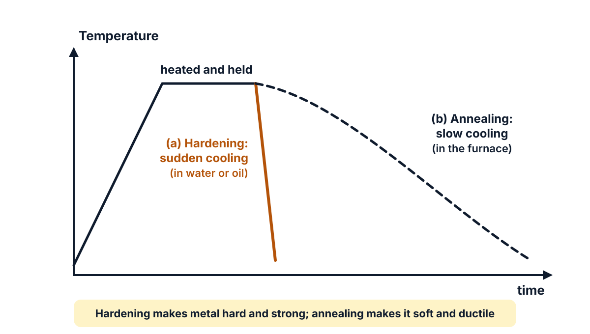
Figure Q2: the same heated metal becomes hard when it is cooled suddenly, and soft when it is cooled slowly.
Exam answer (3 marks)
- (a) Hardening: hardening is the process of heating a metal to a high temperature and then cooling it suddenly (quenching in water or oil); it increases the hardness and strength of the metal.
- (b) Annealing: annealing is the process of heating a metal to a suitable temperature, holding it there and then cooling it slowly; it makes the metal soft and ductile and removes internal stresses.
- Use: hard-drawn copper is used for overhead line conductors (strength); annealed copper is used for winding wires and cables (flexibility and better conductivity).
Key points to write: hardening = heat + sudden cooling, hard and strong; annealing = heat + slow cooling, soft and ductile.
Q3. Distinguish between conductors, insulators and semiconductors. (3 marks)
Understand it first
- Electrons in a solid can have only certain energy values. These allowed values come in groups called energy bands.
- The valence band holds the outer electrons that are tied to their atoms.
- The conduction band holds electrons that are free to move. Only these electrons carry current.
- Between the two bands there may be a gap with no allowed energy. It is the forbidden energy gap, Eg, measured in electron volts (eV).
- The size of this gap decides the type of material:
- Conductor: the bands overlap. There is no gap, so many electrons are always free.
- Semiconductor: a small gap. For silicon it is about 1.1 eV and for germanium about 0.7 eV. Heat lifts a few electrons across.
- Insulator: a large gap, about 5 eV or more. Almost no electron can cross it.
An analogy: think of a two-storey building. Free movement happens only on the upper floor. In a conductor the floors are joined by a ramp, so anyone walks up. In a semiconductor there is a short ladder: a few climb when they get energy. In an insulator there is a high wall with no ladder.
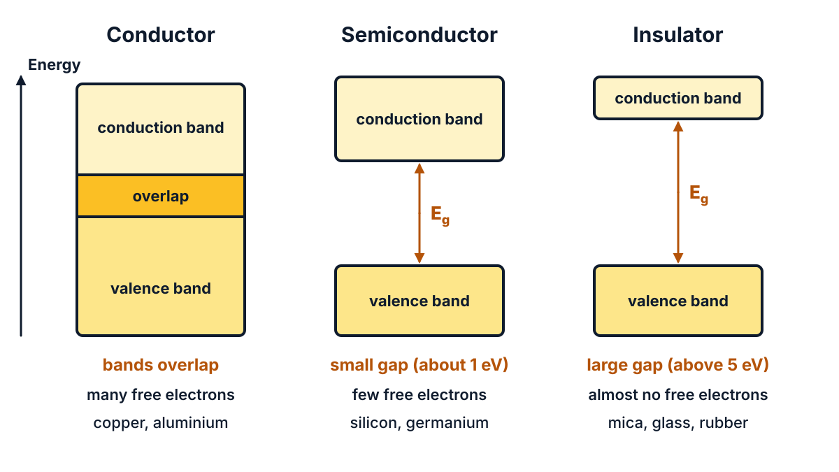
Figure Q3: the forbidden gap is zero for a conductor, small for a semiconductor and large for an insulator.
Exam answer (3 marks)
| Aspect | Conductor | Insulator | Semiconductor |
|---|---|---|---|
| Energy gap | No gap; valence and conduction bands overlap | Very large gap (about 5 eV or more) | Small gap (about 1.1 eV for Si, 0.7 eV for Ge) |
| Conductivity and resistivity | Very high conductivity, very low resistivity | Very low conductivity, very high resistivity | In between; conductivity rises with temperature (negative temperature coefficient) |
| Examples | Copper, aluminium, silver | Mica, glass, rubber, PVC | Silicon, germanium |
Key points to write: energy gap (none, large, small); conductivity (high, very low, medium); examples.
Q4. List any three of di-electric materials. applications (3 marks)
Understand it first
The paper prints the words in a mixed-up order; the question means “List any three applications of dielectric materials”, answered below.
- A dielectric is an insulating material that can be polarised by an electric field. Polarised means its positive and negative charges shift a little and line up with the field.
- It does two jobs. As an insulator it stops current. As a dielectric it stores electric energy, for example between capacitor plates.
- Dielectric constant (relative permittivity, εr) tells how many times a material increases the capacitance compared with air.
- Dielectric strength is the highest voltage per unit thickness a material can stand before it breaks down.
Common dielectrics: air, mica, paper, glass, porcelain, ceramics, transformer oil, PVC and bakelite.
Exam answer (3 marks)
- Capacitors: mica, paper, ceramic and plastic films are used as the dielectric between capacitor plates, to increase capacitance.
- Transformers and machines: transformer oil, impregnated paper and varnish insulate windings and also cool them (oil).
- Cables and insulators: PVC and paper insulate cables; porcelain and glass are used for overhead line insulators and bushings.
Key points to write: capacitors (mica, paper, ceramic); transformers (oil, paper); cables and line insulators (PVC, porcelain, glass).
Q5. Define eddy current loss? (3 marks)
Understand it first
- An iron core of a transformer or motor carries an alternating flux (a flux that changes all the time).
- The iron is itself a conductor. By Faraday’s law (Q6), the changing flux induces small emfs inside the iron.
- These emfs drive circulating currents in closed loops inside the core. They swirl like whirlpools in a river, so they are called eddy currents.
- The eddy currents flow through the resistance of the iron and produce heat (I²R). This wasted power is the eddy current loss.
- To reduce it, the core is built from thin sheets called laminations, each coated with varnish. The thin sheets cut each big loop into many tiny ones with high resistance.
An analogy: a wide pond lets a big whirlpool form. Divide the pond with many thin walls, and only tiny swirls are possible.
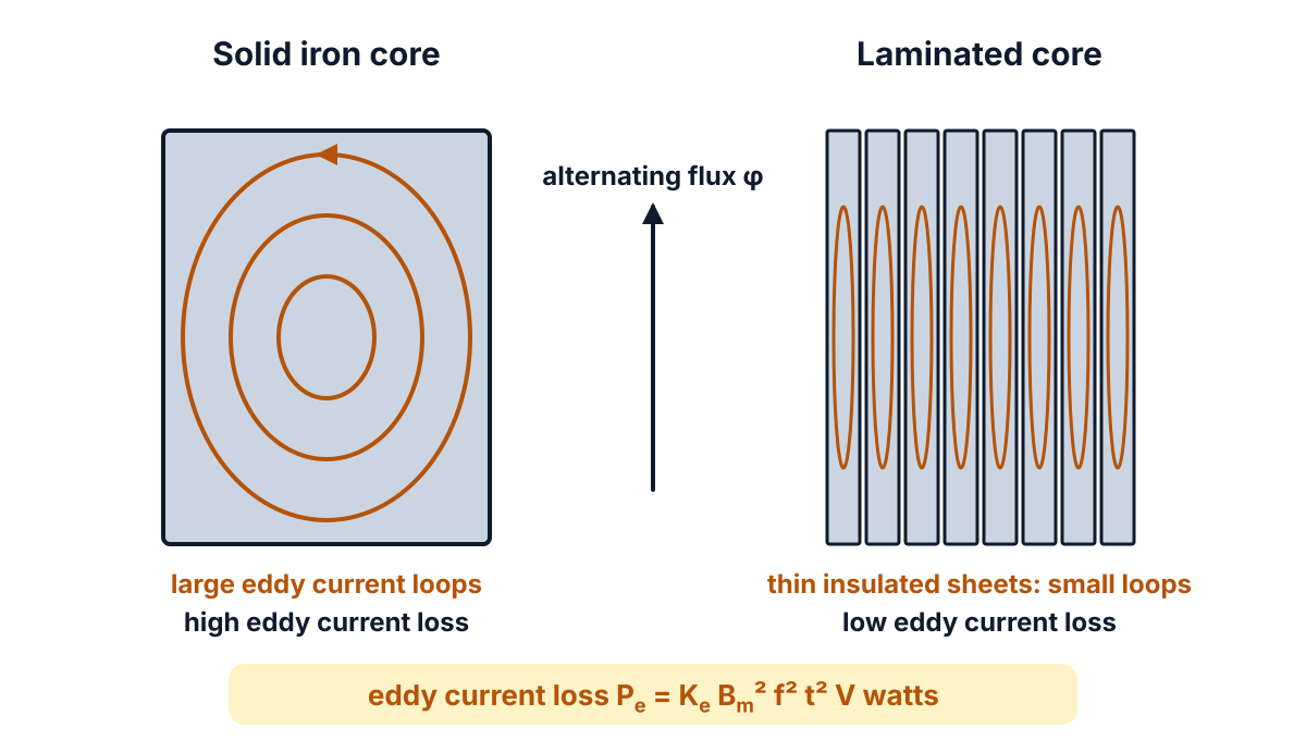
Figure Q5: a solid core lets large eddy current loops flow; thin insulated laminations break them into small loops and cut the loss.
Exam answer (3 marks)
- Definition: when an alternating flux links a magnetic core, emfs are induced in the core and circulating currents called eddy currents flow in it; the power lost as heat due to these currents is called eddy current loss.
- Formula: Pe = Ke Bm² f² t² V watts, where Bm is the maximum flux density, f the frequency, t the thickness of the laminations, V the volume of the core and Ke a constant.
- Reduction: the loss is reduced by using thin laminated cores insulated by varnish, and by using high-resistivity core material such as silicon steel.
Key points to write: circulating currents in the core due to alternating flux; heat loss; Pe ∝ Bm² f² t²; reduced by laminations.
Q6. State Faraday’s laws of electro-magnetic induction. (3 marks)
Understand it first
- Magnetic flux (φ) is the amount of magnetic lines passing through a coil. It is measured in webers (Wb).
- Flux linkage is the flux multiplied by the number of turns, Nφ.
- Electromagnetic induction means producing an emf (a voltage) in a coil by changing the flux through it.
- The key word is change. A magnet held still in a coil gives nothing. Move it in or out, and a voltage appears.
- Faraday found two facts. A change of flux produces an emf (first law). The faster the change, the bigger the emf (second law).
Example: a coil of 100 turns has its flux changed by 0.02 Wb in 0.1 s. Then e = 100 × 0.02 / 0.1 = 20 V.
The same laws, with the same figure, were asked in the EE-105 paper of October 2024.
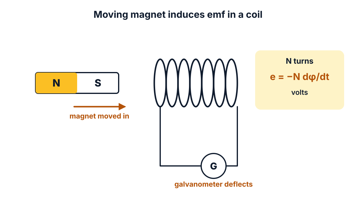
Figure Q6: moving the magnet changes the flux linking the coil, so an emf is induced and the galvanometer deflects.
Exam answer (3 marks)
- First law: whenever the magnetic flux linked with a coil or conductor changes, an emf is induced in it. If the circuit is closed, an induced current flows.
- Second law: the magnitude of the induced emf is equal to the rate of change of flux linkages.
- Formula: e = −N dφ/dt volts, where N is the number of turns and dφ/dt the rate of change of flux in Wb/s; the minus sign shows Lenz’s law (Q8).
Key points to write: change of flux induces emf; emf = rate of change of flux linkages; e = −N dφ/dt.
Q7. Draw the field patterns due to (a) Straight current carrying conductor and (b) Solenoid. (3 marks)
Question (as printed): 7. Draw the field patterns due to (a) Straight current carrying conductor and (b) Solenoid.
Understand it first
- A current always makes a magnetic field around it. We show the field with magnetic lines of force: closed lines that show the direction a north pole would move. These lines were asked in the EE-103 Physics paper of March 2025.
- Dot and cross: a dot (⊙) means current coming out of the page towards you. A cross (⊗) means current going into the page. Think of an arrow: you see its tip coming, its tail feathers going.
- Right hand thumb rule: hold the conductor in your right hand with the thumb along the current. Your curled fingers show the direction of the lines.
- For a straight conductor, the lines are circles centred on the wire. They are close together near the wire (strong field) and spread out further away (weak field).
- A solenoid is a long coil of many turns. The fields of all turns add up. Inside, the lines are straight, parallel and close: a strong, uniform field. Outside, the lines curve round from one end to the other, just like a bar magnet. The end where the lines come out is the N pole.
Exam answer (3 marks)
- (a) Straight conductor: the lines of force are concentric circles in a plane perpendicular to the conductor; anticlockwise for current out of the page and clockwise for current into the page (right hand thumb rule).
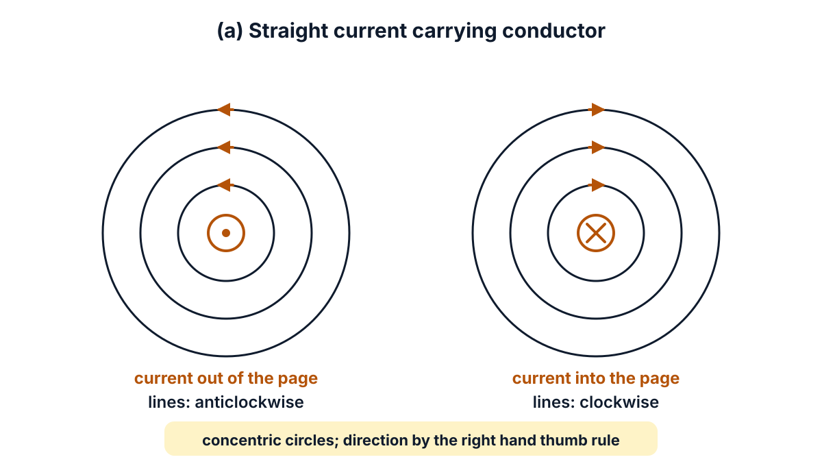
Figure Q7 (a): concentric circular lines round a straight conductor; reversing the current reverses their direction.
- (b) Solenoid: inside the solenoid the lines are straight, parallel and uniform; outside they return from the N end to the S end, so the solenoid behaves like a bar magnet.
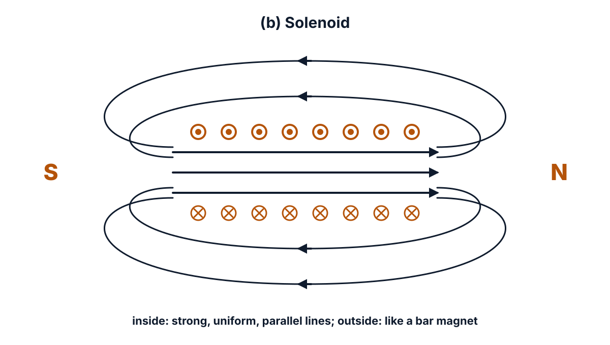
Figure Q7 (b): a solenoid with current out of the page on top and into the page below; the lines run S to N inside and N to S outside.
- Points to note: lines never cross each other; they are crowded where the field is strong (near the wire, inside the solenoid); the field strength rises with the current and, for a solenoid, with the number of turns.
Key points to write: concentric circles for a straight wire; uniform parallel lines inside a solenoid, bar-magnet pattern outside; right hand thumb rule.
Q8. State Len’z law. (3 marks)
Understand it first
The paper prints “Len’z law”; it means Lenz’s law.
- Faraday’s laws (Q6) tell us that a changing flux induces an emf and how big it is.
- Lenz’s law tells us the direction of the induced emf and current.
- The rule: the induced current always flows in such a direction that it opposes the change that produced it.
- Push the N pole of a magnet towards a coil. The induced current makes the near face of the coil a N pole too. Like poles repel, so the coil pushes back on the magnet.
- Pull the magnet away. Now the near face becomes a S pole, which pulls the magnet back.
- Why must it oppose? Because of the law of conservation of energy. You must do work against this push. That work is what becomes electrical energy. If the coil helped the magnet instead, we would get energy for nothing, which is impossible.
An analogy: a door with a spring closer. Push it open, and it pushes back. Let go while it is closing, and it resists slamming. It always fights the change.
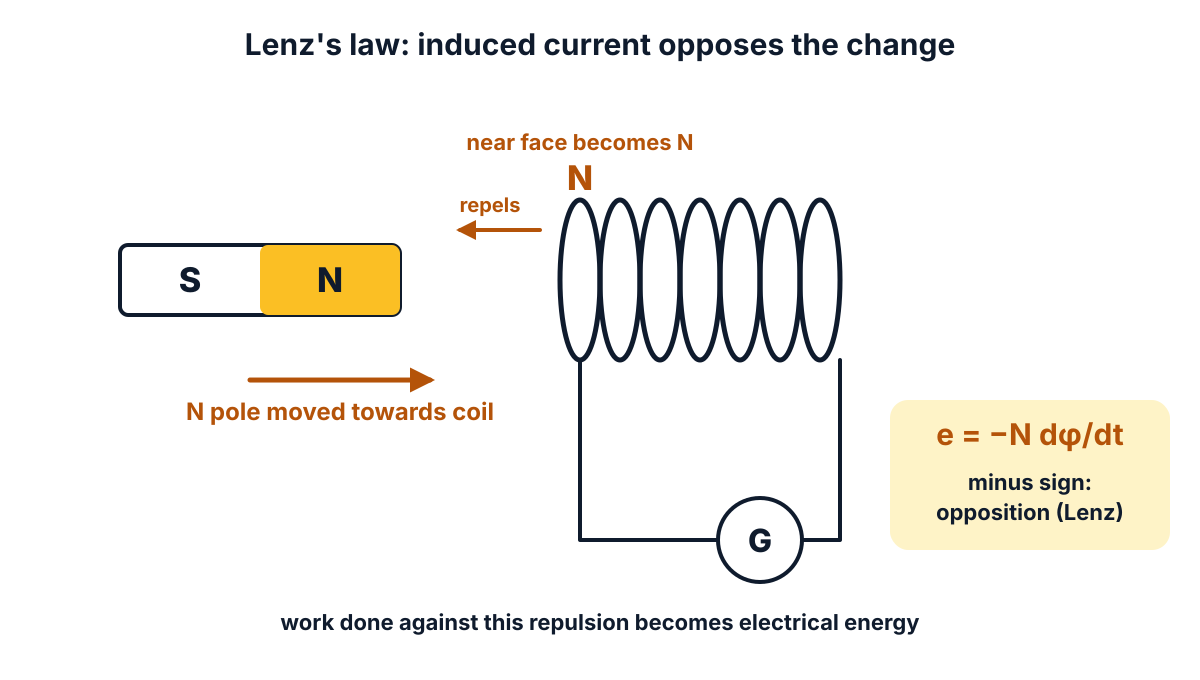
Figure Q8: pushing the N pole in makes the near face of the coil a N pole, which repels the magnet and opposes the change.
Exam answer (3 marks)
- Statement: the direction of the induced emf (or current) is always such that it opposes the cause, that is, the change in flux, which produces it.
- Formula: this opposition is shown by the minus sign in e = −N dφ/dt volts.
- Example and reason: when the N pole of a magnet approaches a coil, the near face of the coil becomes a N pole and repels the magnet; the law follows from the law of conservation of energy.
Key points to write: induced emf opposes the change causing it; minus sign in e = −N dφ/dt; follows from conservation of energy.
Q9. State Coulomb’s laws of electrostatics. (3 marks)
Understand it first
- Electric charge (Q) is measured in coulombs (C). Like charges (+ and +, or − and −) repel. Unlike charges (+ and −) attract.
- A point charge is a charged body so small compared with the distance between charges that we treat it as a point.
- Permittivity (ε) tells how easily a medium allows electric flux. ε = ε0εr, where ε0 = 8.854 × 10⁻¹² F/m is the permittivity of free space and εr is the relative permittivity of the medium.
- Coulomb measured how the force between two charges depends on the charges and on the distance.
His results are two laws:
- The force is attraction for unlike charges and repulsion for like charges.
- The force is proportional to the product of the charges, and inversely proportional to the square of the distance. Double the distance and the force falls to one quarter.
Example: Q1 = 2 µC and Q2 = 3 µC, 0.3 m apart in air. Then d² = 0.09, the top line is 9 × 10⁹ × 2 × 10⁻⁶ × 3 × 10⁻⁶ = 0.054, and F = 0.054 / 0.09 = 0.6 N of repulsion.
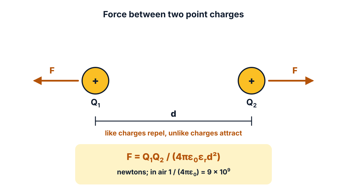
Figure Q9: two like charges a distance d apart repel each other with equal and opposite forces F.
Exam answer (3 marks)
- First law: like charges repel each other and unlike charges attract each other.
- Second law: the force between two point charges is directly proportional to the product of the charges and inversely proportional to the square of the distance between them: F ∝ Q1Q2 / d².
- Formula: F = Q1Q2 / (4πε0εrd²) newtons; in air (εr = 1), 1 / (4πε0) = 9 × 10⁹, so F = 9 × 10⁹ Q1Q2 / d² newtons.
Key points to write: like repel, unlike attract; F ∝ Q1Q2 / d²; F = Q1Q2 / (4πε0εrd²).
Q10. Define the terms (a) Electric flux, (b) Flux density related to electrostatics. (3 marks)
Understand it first
- A charge spreads an electric field around it. We draw the field as lines leaving positive charges and ending on negative charges.
- Electric flux (ψ, psi) is the total number of these lines. In SI units, a charge of Q coulombs sends out a flux of exactly Q coulombs. So flux is measured in coulombs.
- Density means “how much per unit area”, like people per square kilometre.
- Electric flux density (D) is the flux passing through one square metre held at right angles to the flux. Unit: C/m².
- D is linked to the electric field intensity E by D = ε0εrE.
An analogy: water from a garden sprinkler. All the water is the flux. The water falling on one square metre of lawn is the flux density. Near the sprinkler it is heavy; far away it is thin, because the same water spreads over a larger area.
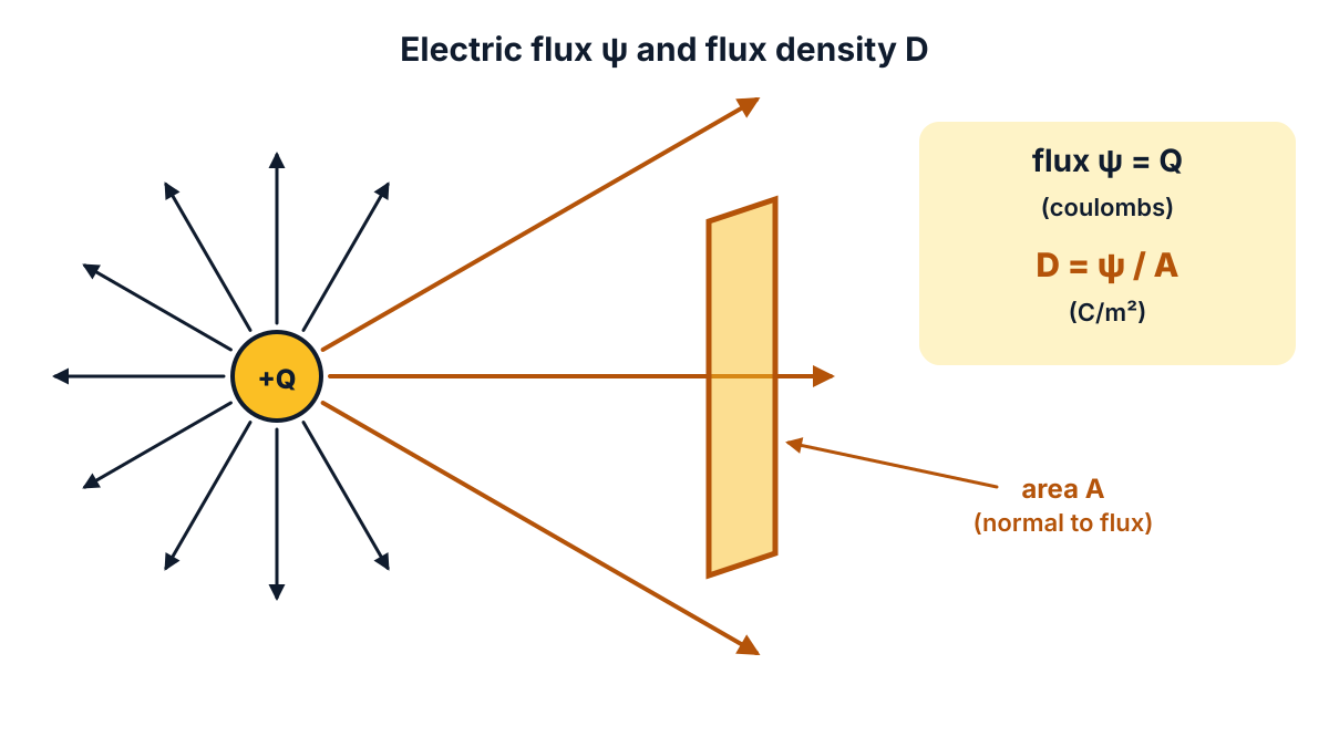
Figure Q10: a charge Q sends out a flux ψ = Q; the part crossing an area A held normal to it gives D = ψ / A.
Exam answer (3 marks)
- (a) Electric flux: the total number of lines of force coming out of a charged body is called electric flux (ψ); a charge of Q coulombs gives a flux of Q coulombs, so its unit is the coulomb.
- (b) Flux density: the electric flux passing normally through unit area is called electric flux density: D = ψ / A, unit C/m².
- Relation: for a point charge Q at distance r, D = Q / (4πr²); and D = ε0εrE, where E is the field intensity in V/m.
Key points to write: flux = total lines, ψ = Q, in coulombs; D = ψ / A in C/m²; D = ε0εrE.
Q11. State the properties and applications of copper and aluminium. (10 marks)
Understand it first
- Low resistivity materials (good conductors) carry current with very little loss. The two most used are copper and aluminium.
- Conductivity is the opposite of resistivity: how easily a material lets current flow.
- Density is mass per unit volume. A low density means a light conductor.
The numbers that decide the choice, from standard resistivity tables and the data pages for copper and aluminium:
| Property | Copper (annealed) | Aluminium |
|---|---|---|
| Resistivity at 20 °C | 1.72 × 10⁻⁸ Ω m | 2.82 × 10⁻⁸ Ω m |
| Density | about 8.9 g/cm³ | about 2.7 g/cm³ |
| Melting point | about 1085 °C | about 660 °C |
What these numbers mean:
- Copper conducts better. Aluminium’s conductivity is 1.72 / 2.82 = 0.61 of copper’s, about 61%.
- So for the same resistance, an aluminium wire needs 2.82 / 1.72 = 1.64 times the cross-section.
- But aluminium is so light that even this thicker wire weighs only about half as much: 1.64 × 2.70 / 8.935 = 0.495.
- That is why copper wins where space is small (windings, house wiring) and aluminium wins where weight matters (overhead lines).
An analogy: copper is a narrow, heavy road. Aluminium is a wider road made of light material. Both carry the same traffic.
Exam answer (10 marks)
The split assumed is 5 marks for copper and 5 marks for aluminium.
(a) Copper (5 marks)
- Electrical properties: very high conductivity; resistivity about 1.72 × 10⁻⁸ Ω m at 20 °C (annealed), second only to silver.
- Physical properties: reddish-brown, heavy (density about 8.9 g/cm³), melting point about 1085 °C, good conductor of heat.
- Mechanical properties: ductile and malleable, easily drawn into thin wires; can be soldered, brazed and welded easily; good resistance to corrosion.
- Applications (windings and wiring): windings of motors, generators and transformers; house wiring wires, flexible cords and power cables.
- Applications (others): commutator segments, bus bars, switch contacts, earthing strips and overhead lines (hard-drawn copper).
(b) Aluminium (5 marks)
- Electrical properties: good conductor; resistivity about 2.82 × 10⁻⁸ Ω m, so its conductivity is about 61% of copper’s.
- Physical properties: silvery white and very light (density about 2.7 g/cm³), melting point about 660 °C; for equal conductance it weighs about half as much as copper.
- Mechanical properties: soft and ductile but weaker than copper; difficult to solder; forms a thin oxide layer that protects it from further corrosion; cheaper than copper.
- Applications (lines): overhead transmission and distribution lines as ACSR (aluminium conductor steel reinforced) and AAAC (all aluminium alloy conductor); bus bars.
- Applications (others): power cables, cable sheaths, windings of some transformers and motors, and squirrel cage rotor bars of induction motors.
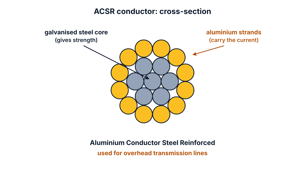
Figure Q11: in an ACSR conductor the steel core gives strength and the aluminium strands carry the current.
Conclusion: copper is preferred where space is limited and high conductivity is needed; aluminium is preferred where low weight and low cost matter, as in overhead lines.
Q12. Distinguish between intrinsic and extrinsic semi-conductors. (10 marks)
Understand it first
- A semiconductor conducts better than an insulator but worse than a conductor. Silicon (Si) and germanium (Ge) are the common ones. Each atom has 4 outer (valence) electrons.
- In the crystal, each atom shares its 4 electrons with 4 neighbours. A shared pair is a covalent bond.
- An intrinsic semiconductor is a pure semiconductor, with no impurity added.
- At room temperature, heat breaks a few bonds. Each broken bond gives one free electron and leaves one empty place, a hole. A hole acts like a moving positive charge.
- So in a pure crystal the number of free electrons equals the number of holes (n = p). There are very few of either, so conductivity is low.
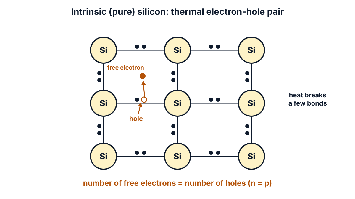
Figure Q12 (a): in pure silicon, heat breaks a bond and makes one free electron and one hole, so n = p.
- Doping means adding a very small, controlled amount of another element (an impurity). The doped crystal is an extrinsic semiconductor.
- A pentavalent impurity (5 valence electrons: phosphorus, arsenic, antimony) gives one extra free electron per atom. This makes an N-type semiconductor. Its formation was asked in the EE-103 Physics paper of March 2026.
- A trivalent impurity (3 valence electrons: boron, aluminium, gallium) leaves one hole per atom. This makes a P-type semiconductor.
- Majority carriers are the carriers present in large numbers; minority carriers are the few of the other kind.
An analogy: a pure crystal is a hall where every seat is taken and only a few people stand up now and then. Doping brings in extra people with no seat (N-type), or leaves some seats empty (P-type). Now people move about much more.
Exam answer (10 marks)
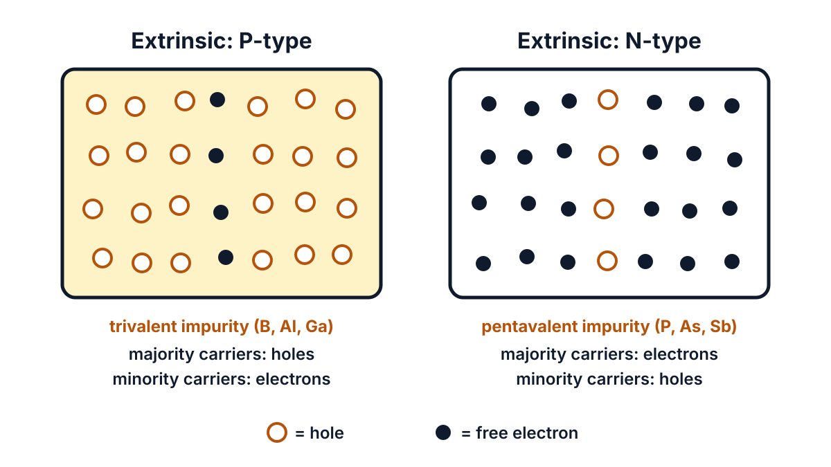
Figure Q12 (b): extrinsic semiconductors; holes are the majority carriers in P-type and free electrons in N-type.
| No | Aspect | Intrinsic semiconductor | Extrinsic semiconductor |
|---|---|---|---|
| 1 | Definition | A semiconductor in its pure form | A semiconductor to which a small amount of impurity is added (doped) |
| 2 | Impurity | No impurity | Trivalent (B, Al, Ga) or pentavalent (P, As, Sb) impurity |
| 3 | Carrier numbers | Free electrons = holes (n = p) | Not equal: electrons ≫ holes in N-type, holes ≫ electrons in P-type |
| 4 | Majority carriers | No majority carriers | Electrons in N-type, holes in P-type |
| 5 | Conductivity | Low | High; much higher than intrinsic |
| 6 | Control of conductivity | Depends only on temperature | Depends on the amount of doping and on temperature |
| 7 | Types | Only one type | Two types: P-type and N-type |
| 8 | Fermi level / energy levels | Fermi level in the middle of the forbidden gap | Extra donor level near the conduction band (N-type) or acceptor level near the valence band (P-type) |
| 9 | Examples | Pure silicon, pure germanium | Si doped with arsenic (N-type), Si doped with boron (P-type) |
| 10 | Use | Little practical use as such | Used to make diodes, transistors and ICs |
Conclusion: an intrinsic semiconductor is pure and conducts poorly with equal electrons and holes; doping it gives an extrinsic (P or N type) semiconductor whose conductivity can be controlled.
Q13. State the effects of the following on P.V.C. (a) Filler, (b) Stabilizer, (c) Plasticizer and (d) Additives. (10 marks)
Question (as printed): 13. State the effects of the following on P.V.C. (a) Filler, (b) Stabilizer, (c) Plasticizer and (d) Additives. 10
Understand it first
- PVC means polyvinyl chloride. It is a thermoplastic: it softens on heating and hardens on cooling, so it can be moulded again and again.
- Pure PVC resin is hard, stiff and brittle. It also slowly breaks down when it is heated or kept in sunlight. On breaking down it gives off hydrochloric acid gas.
- So makers never use pure PVC for cables. They mix four kinds of substances into it. The mixture is called a PVC compound.
- Each substance has one job:
- Filler: a cheap powder that adds bulk.
- Stabilizer: a protector against heat and light.
- Plasticizer: a softener that makes PVC flexible.
- Additives: extras for special needs, such as colour or fire resistance.
An analogy: making chapati dough. Flour alone is dry and cracks (pure PVC). Water makes it soft (plasticizer). A little oil keeps it from drying out (stabilizer). Salt and spices are the extras (additives). The recipe is changed to suit the use.
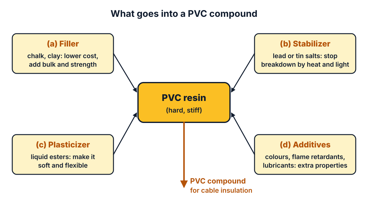
Figure Q13: PVC resin is mixed with filler, stabilizer, plasticizer and additives to make the compound used for cables.
The insulation and wiring uses of PVC were covered in the EE-105 paper of October 2024.
Exam answer (10 marks)
PVC (polyvinyl chloride) is a thermoplastic insulating material. Pure PVC is hard and unstable, so the following substances are added. The split assumed is 2.5 marks for each part, written as 2 to 3 points each.
(a) Filler
- What it is: an inert powder such as china clay, chalk (calcium carbonate) or talc, added to the PVC resin.
- Effect on cost and strength: it reduces the cost of the compound and adds bulk, hardness and mechanical strength.
- Effect on electrical properties: a suitable filler improves the insulation resistance and heat resistance, but too much filler lowers flexibility and dielectric strength.
(b) Stabilizer
- What it is: compounds of lead, tin, barium or calcium added in small amounts.
- Effect: they stop the breakdown (degradation) of PVC by heat during processing and by heat and sunlight during service, by absorbing the hydrochloric acid gas given off.
- Result: the PVC keeps its colour, flexibility and electrical properties for a long life.
(c) Plasticizer
- What it is: a high-boiling liquid, usually an ester such as a phthalate, mixed into the resin.
- Effect: it makes the hard, brittle PVC soft and flexible and lowers its softening temperature, so cables can be bent easily; but too much plasticizer reduces insulation resistance and dielectric strength.
(d) Additives
- What they are: small amounts of colouring pigments, flame retardants, lubricants and anti-oxidants.
- Effect: pigments give colour codes to cores; flame retardants make PVC self-extinguishing; lubricants help in extrusion; anti-oxidants and UV absorbers protect against ageing.
Conclusion: by choosing the right amounts of filler, stabilizer, plasticizer and additives, PVC is made cheap, flexible, stable and safe for cables, wires and sleeves.
Q14. State the properties and applications of (a) Impregnated paper and (b) Glass. (10 marks)
Question (as printed): 14. State the properties and applications of (a) Impregnated paper and (b) Glass. 10
Understand it first
- Plain paper is made of cellulose fibres. It is cheap and insulates well when dry. But it is hygroscopic: it soaks up moisture from the air, and wet paper is a poor insulator.
- Impregnated means soaked through. The paper is dried, then soaked in insulating oil, varnish, wax or resin. The oil fills the tiny air spaces and keeps moisture out. This raises its dielectric strength (the voltage it can stand without breaking down).
- Glass is a hard, transparent, inorganic material made mainly of silica (sand) with soda and lime. It does not absorb water and does not burn.
- Toughened glass is glass heated and then cooled quickly with air jets. Its surface is in compression, so it is much stronger. Overhead line insulators use toughened glass.
- Impregnated paper belongs to class A insulation (105 °C). Glass belongs to the highest class, C (above 180 °C), as listed in the thermal classes of insulation.
An analogy: a dry sponge soaks up water. Fill it with oil first, and water cannot enter. That is impregnation. Glass is like a glazed plate: water simply runs off.
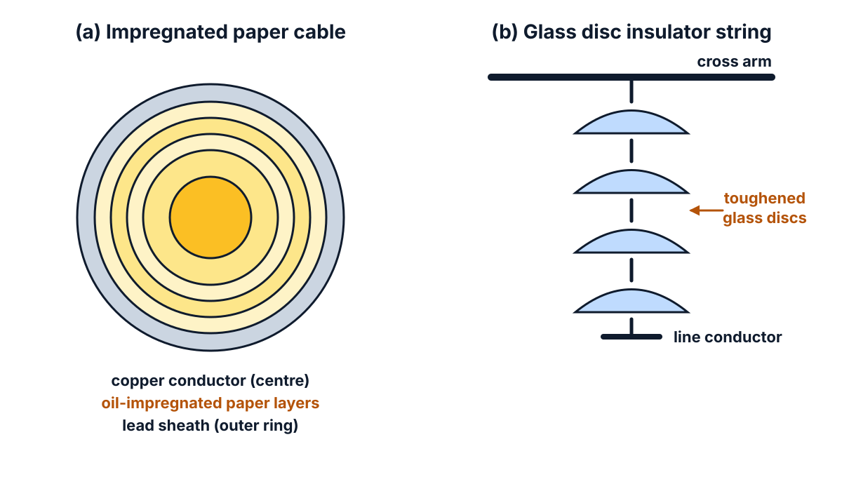
Figure Q14: impregnated paper insulates a high voltage cable (left); toughened glass discs insulate an overhead line (right).
Exam answer (10 marks)
The split assumed is 5 marks for impregnated paper and 5 marks for glass.
(a) Impregnated paper (5 marks)
- Meaning: paper (cellulose) that is dried and then impregnated with insulating oil, varnish, wax or resin to remove moisture and fill the air spaces.
- Electrical properties: high dielectric strength, high insulation resistance and low dielectric loss after impregnation.
- Other properties: cheap, light, flexible and easy to wind in layers; impregnation makes it non-hygroscopic; class A insulation (105 °C).
- Applications (cables): insulation of high voltage underground power cables (paper-insulated, lead-sheathed cables).
- Applications (other): dielectric of paper capacitors, and insulation between layers of transformer windings and coils.
(b) Glass (5 marks)
- Composition: an inorganic material made mainly of silica with oxides of sodium, calcium, boron or lead.
- Electrical properties: high dielectric strength and high resistivity; low dielectric loss; insulation resistance stays high because it does not absorb moisture.
- Other properties: hard, transparent, non-hygroscopic, non-inflammable, resistant to most chemicals and weather, withstands high temperature (class C); but brittle and weak against mechanical shock unless toughened.
- Applications (power): overhead line insulators (toughened glass pin and disc insulators), bushings, and glass fibre tapes and sleeves for winding insulation.
- Applications (other): bulbs of electric lamps and tubes, glass capacitors, and glass fibre boards for printed circuits.
Conclusion: impregnated paper is used for high voltage cables and capacitors; glass is used where moisture, heat and weather would spoil organic insulation, as in line insulators and lamps.
Q15. Explain Hysteresis loop with a neat sketch. (10 marks)
Understand it first
- Magnetising force (H) is the “push” that magnetises iron. It comes from the current in a coil wound on the iron. Unit: ampere-turns per metre (AT/m).
- Flux density (B) is the result: how strongly the iron is magnetised. Unit: tesla (T) or Wb/m².
- A ferromagnetic material such as iron is made of tiny regions called domains. Each domain is already a small magnet, but the domains point in different directions.
- As H rises, the domains turn to line up with H, and B rises. When nearly all are lined up, B stops rising. This is saturation.
- Now reduce H to zero. The domains do not all turn back. Some magnetism stays. This is residual magnetism or retentivity, Br.
- To remove it, you must apply H in the opposite direction. The reverse H needed to bring B to zero is the coercive force, Hc.
- Taking H through one full cycle (positive, zero, negative, zero, positive) gives a closed curve. This curve is the hysteresis loop. “Hysteresis” means “lagging behind”: B always lags behind H.
- Turning the domains back and forth uses energy, which appears as heat. The energy lost per cycle equals the area of the loop. This is the hysteresis loss.
An analogy: a thick bush on a path. You push through it one way, and the branches stay bent that way (residual magnetism). To straighten them, you must push from the other side (coercive force). The effort spent every time is the loss.
Exam answer (10 marks)
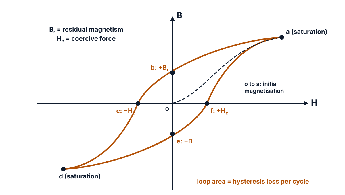
Figure Q15 (a): the hysteresis loop a-b-c-d-e-f-a; Br is the residual magnetism, Hc the coercive force, and the loop area the loss per cycle.
- Definition: the hysteresis loop is the closed B-H curve obtained when a ferromagnetic material is taken through one complete cycle of magnetisation; it shows that B lags behind H (hysteresis).
- Initial magnetisation (o to a): as H is increased from zero, B rises along the curve oa until the material is saturated at a.
- Residual magnetism (a to b): when H is reduced to zero, B does not return to zero but falls only to ob = +Br, called residual magnetism or retentivity.
- Coercive force (b to c): to make B zero, a reverse magnetising force oc = −Hc must be applied; this is called the coercive force or coercivity.
- Negative saturation (c to d): increasing H further in the reverse direction saturates the material in the opposite direction at d.
- Return path (d to e to f to a): reducing H to zero leaves −Br at e; a positive force +Hc at f makes B zero, and increasing H again brings the material back to saturation at a, closing the loop.
- Hysteresis loss: energy is spent in turning the domains in each cycle; it is lost as heat, and the loss per cycle per unit volume is proportional to the area of the loop.
- Steinmetz equation: hysteresis loss Wh = η Bmax1.6 f V watts, where η is the hysteresis coefficient, f the frequency and V the volume of the material.
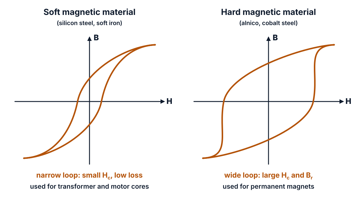
Figure Q15 (b): a soft material has a narrow loop (low loss); a hard material has a wide loop (strong, lasting magnetism).
- Soft magnetic materials: narrow loop, small Hc and low hysteresis loss (silicon steel, soft iron); used for cores of transformers, motors and generators.
- Hard magnetic materials: wide loop, large Hc and large Br (alnico, cobalt steel); used for permanent magnets in meters and loudspeakers.
Conclusion: the hysteresis loop gives the residual magnetism, the coercive force and the hysteresis loss of a material, and so tells us whether it suits a core (narrow loop) or a permanent magnet (wide loop). The soft and hard material types also came in the EE-105 paper of October 2024.
Q16. Explain dynamically and statically induced E.M.F. (10 marks)
Understand it first
- By Faraday’s law (Q6), an emf is induced whenever the flux linking a conductor or coil changes.
- The flux can change in two ways. Either something moves, or the current that makes the flux changes while nothing moves.
- Dynamically induced emf: the conductor moves through a steady field, or the field moves past a still conductor. The conductor “cuts” the lines of force. This is how generators work.
- Statically induced emf: nothing moves. The current in a coil changes, so its flux changes. This is how transformers work. It has two kinds:
- Self-induced emf: the changing current of a coil induces an emf in the same coil.
- Mutually induced emf: the changing current of one coil induces an emf in a second coil nearby.
- Self-inductance (L) and mutual inductance (M), both in henry (H), tell how much emf a coil gets per unit rate of change of current.
- Fleming’s right hand rule gives the direction of a dynamically induced emf: stretch the thumb, forefinger and middle finger of the right hand at right angles. Thumb = motion, forefinger = field, middle finger = induced emf (current).
Example of dynamic emf: a conductor 0.5 m long moves at 10 m/s at right angles to a field of 0.8 T. Then e = 0.8 × 0.5 × 10 = 4 V. If it moves at 30° to the field, e = 4 × 0.5 = 2 V.
An analogy: you can get wet in rain in two ways. You can run through still rain (dynamic: you move). Or you can stand still while the rain gets heavier (static: the field changes).
Exam answer (10 marks)
Induced emfs are of two kinds: (a) dynamically induced emf and (b) statically induced emf.
(a) Dynamically induced emf
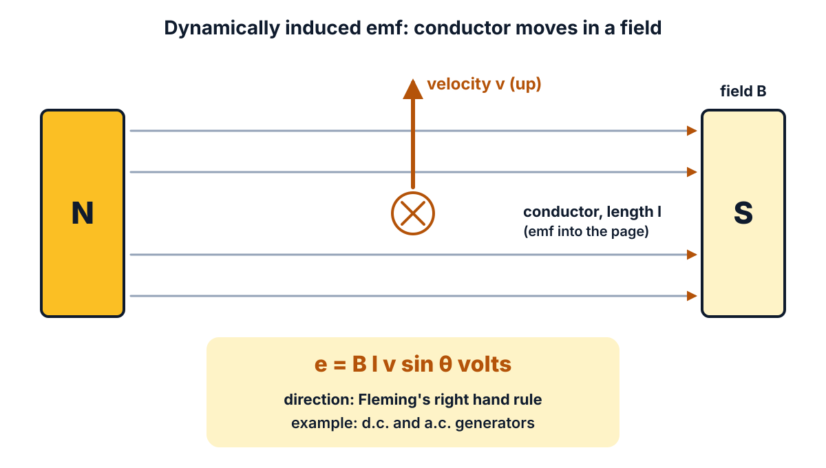
Figure Q16 (a): a conductor moving across a field cuts the lines of force, so an emf e = B l v sin θ is induced in it.
- Definition: the emf induced in a conductor when the conductor moves in a stationary magnetic field (or the field moves past a stationary conductor), so that it cuts the lines of force, is called dynamically induced emf.
- Derivation: let a conductor of length l metres move with velocity v m/s at an angle θ to a field of flux density B Wb/m². In time dt it moves a distance v dt and sweeps an area l v dt, so the flux cut is dφ = B l v dt sin θ.
- Formula: by Faraday’s law, e = dφ/dt = B l v sin θ volts; it is maximum (B l v) when the conductor moves at right angles to the field and zero when it moves along the field.
- Direction: given by Fleming’s right hand rule (thumb = motion, forefinger = field, middle finger = induced emf).
- Example: the emf induced in the armature conductors of DC and AC generators.
(b) Statically induced emf
- Definition: the emf induced in a coil when the conductor and the coil are stationary but the flux linking the coil changes because the current changes is called statically induced emf; it is of two types, self-induced and mutually induced.
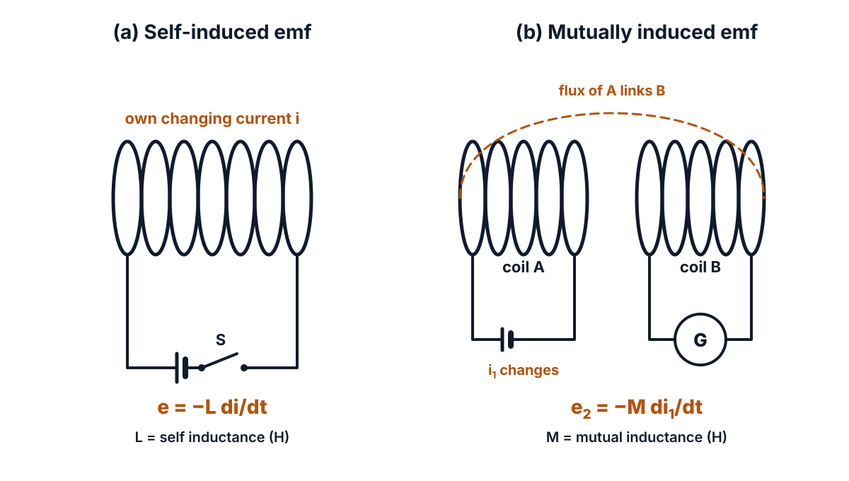
Figure Q16 (b): self-induced emf appears in the coil whose current changes; mutually induced emf appears in the neighbouring coil.
- Self-induced emf: when the current in a coil changes, its own flux changes and an emf is induced in the same coil, opposing the change (Lenz’s law): e = −L di/dt volts.
- Self-inductance: L = Nφ / I henry; a coil has 1 H when a current changing at 1 A/s induces 1 V in it. Example: the choke of a tube light.
- Mutually induced emf: when the current in coil A changes, part of its changing flux links a nearby coil B and induces an emf in B: e2 = −M di1/dt volts.
- Mutual inductance and example: M = N2φ12 / I1 henry; it depends on the turns, the core and the closeness of the coils. Example: transformers and ignition coils work on mutually induced emf.
Conclusion: a dynamically induced emf needs motion (generators); a statically induced emf needs only a changing current (self-induced in chokes, mutually induced in transformers).
Q17. (a) Develop an expression for the energy stored in a magnetic field. (10 marks)
Question (as printed): 17. (a) Develop an expression for the energy stored in a magnetic field. 5
(b) Compare magnetic circuit with electric circuit in any five aspects. 5
Understand it first
Part (a), energy in a magnetic field:
- An inductor is a coil of wire. Its self-inductance L, in henry, tells how strongly it opposes a change in its own current.
- When a coil is switched on, its current rises from zero to the final value I over a short time.
- While the current rises, a self-induced emf e = L di/dt appears. By Lenz’s law it opposes the rise. It is called the back emf.
- The supply must push current against this back emf. That is work done, and it is stored in the magnetic field of the coil.
- When the current is switched off, the field collapses and gives the energy back. That is the spark at a switch in an inductive circuit.
Example: a coil of L = 0.5 H carrying I = 4 A stores W = ½ × 0.5 × 4² = 0.5 × 0.5 × 16 = 4 J. The same derivation was asked as a full 10-mark question in the EE-105 paper of October 2024.
Part (b), magnetic circuit:
- A magnetic circuit is the closed path followed by magnetic flux, for example an iron ring with a coil on it.
- Magnetomotive force (mmf) is the “push” that drives flux. mmf = N I ampere-turns (AT), where N is the number of turns and I the current.
- Reluctance (S) is the opposition of the path to flux. S = l / (μ0μrA) AT/Wb.
- Then flux φ = mmf / S. This looks exactly like Ohm’s law, I = emf / R. That is why the two circuits are compared.
An analogy: flux is like water in a closed loop of pipe. The pump is the mmf. A narrow pipe is a high reluctance.
Exam answer (10 marks)
(a) Energy stored in a magnetic field (5 marks)
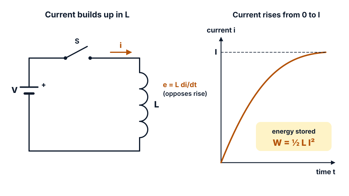
Figure Q17 (a): when S is closed the current rises from 0 to I against the back emf L di/dt, and the work done is stored in the field.
- Set-up: consider a coil of self-inductance L henry connected to a DC supply through a switch S; when S is closed, the current rises from zero to its final value I.
- Back emf and power: at any instant the current is i, rising at di/dt; the self-induced emf e = L di/dt opposes it, so the supply gives power p = e × i = L i (di/dt) watts.
- Energy in time dt: dW = p dt = L i di.
- Total energy: W = ∫₀ᴵ L i di = L [i² / 2] from 0 to I = ½ L I².
- Result: W = ½ L I² joules, stored in the magnetic field of the coil and returned when the current falls to zero.
(b) Comparison of magnetic circuit with electric circuit (5 marks)
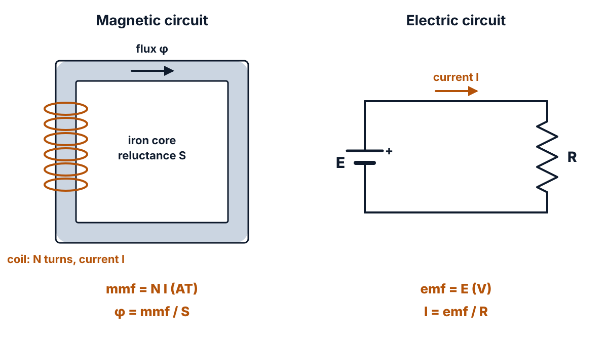
Figure Q17 (b): mmf drives flux through reluctance just as emf drives current through resistance.
| No | Magnetic circuit | Electric circuit |
|---|---|---|
| 1 | Closed path of magnetic flux | Closed path of electric current |
| 2 | Driving force: mmf = N I, in ampere-turns (AT) | Driving force: emf, in volts (V) |
| 3 | Result: flux φ, in webers (Wb) | Result: current I, in amperes (A) |
| 4 | Opposition: reluctance S = l / (μ0μrA), in AT/Wb | Opposition: resistance R = ρl / A, in ohms (Ω) |
| 5 | Flux = mmf / reluctance; energy is needed only to set up the flux, not to keep it, and flux does not actually flow | Current = emf / resistance; energy is spent continuously as long as current flows (I²R loss), and current actually flows |
Answer: (a) W = ½ L I² joules; (b) mmf, flux and reluctance correspond to emf, current and resistance.
Q18. (a) Derive an expression for equivalent capacitance when two capacitors are connected in parallel. (10 marks)
Question (as printed): 18. (a) Derive an expression for equivalent capacitance when two capacitors are connected in parallel. 5
(b) State different types of capacitors with its uses. 5
Understand it first
Part (a), capacitors in parallel:
- A capacitor stores charge. Capacitance C is the charge stored per volt: C = Q / V, in farads (F). Small capacitors are given in microfarads (µF).
- Parallel connection means both capacitors are connected across the same two points. So both get the same voltage V.
- Each stores its own charge: Q1 = C1V and Q2 = C2V. The supply gives the total charge Q = Q1 + Q2.
- Capacitors in parallel simply add up, like resistors in series. Resistors follow the opposite rule; their series and parallel rules were compared in the EE-106 paper of March 2025.
Example: C1 = 4 µF and C2 = 6 µF across 100 V. Q1 = 4 × 100 = 400 µC, Q2 = 6 × 100 = 600 µC, total Q = 1000 µC. So C = 1000 / 100 = 10 µF, which is 4 + 6.
An analogy: two buckets placed side by side under the same tap level. Together they hold the sum of both.
Part (b), types: capacitors are named by their dielectric: paper, mica, ceramic, plastic film, electrolytic, or air (variable). The dielectric decides the size, voltage rating and frequency at which a capacitor works well.
Exam answer (10 marks)
(a) Capacitors in parallel (5 marks)
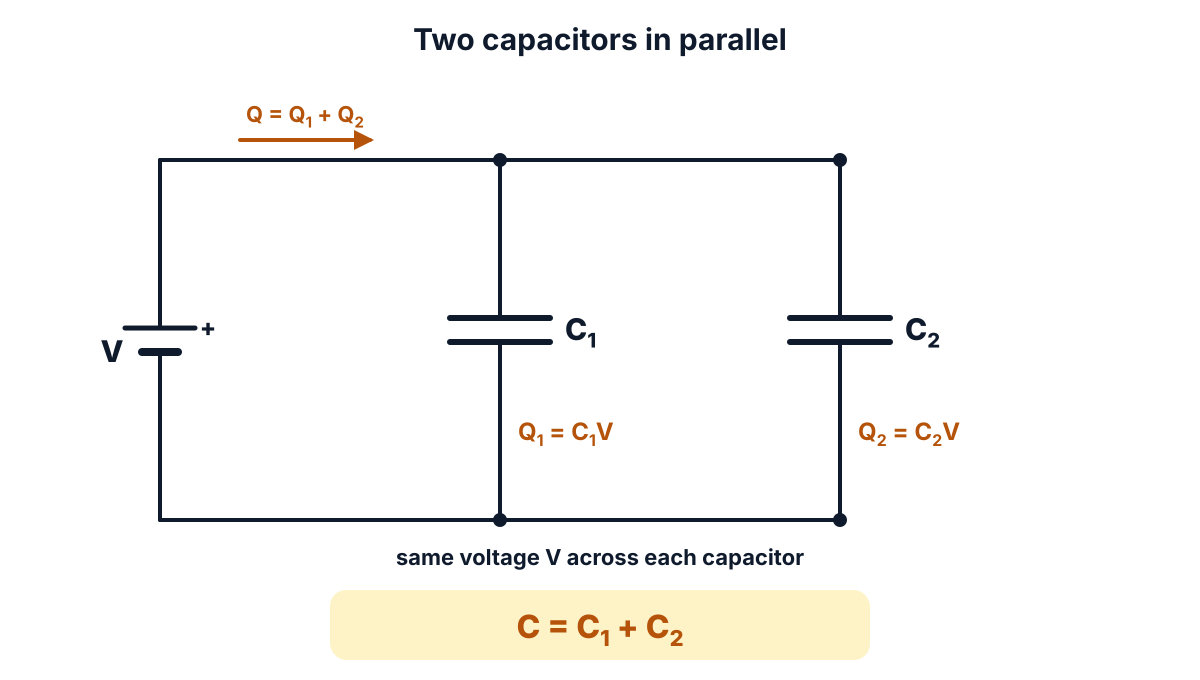
Figure Q18 (a): both capacitors have the same voltage V, and their charges add up to the total charge Q.
- Set-up: let two capacitors of capacitance C1 and C2 farads be connected in parallel across a supply of V volts.
- Same voltage: in parallel, the voltage across each capacitor is the same, V.
- Charges: Q1 = C1V and Q2 = C2V; the total charge supplied is Q = Q1 + Q2 = C1V + C2V.
- Equivalent capacitor: if C is the equivalent capacitance, Q = CV; so CV = C1V + C2V.
- Result: dividing by V, C = C1 + C2; the equivalent capacitance is the sum of the individual capacitances (for n capacitors, C = C1 + C2 + … + Cn).
(b) Types of capacitors and their uses (5 marks)
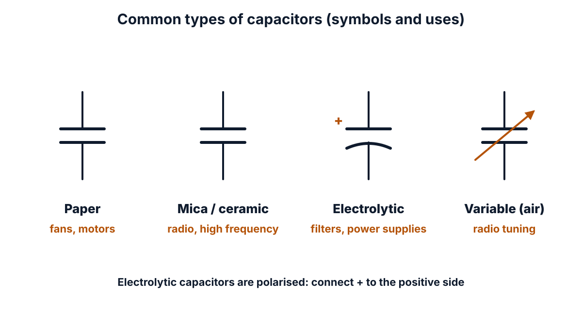
Figure Q18 (b): symbols of fixed, electrolytic (polarised) and variable capacitors.
- Paper capacitor: impregnated paper between aluminium foils, rolled up; used in ceiling fans, single-phase motors and power factor correction.
- Mica capacitor: thin mica sheets between metal plates; very stable and low loss; used in radio and high frequency circuits and oscillators.
- Ceramic capacitor: a ceramic disc with silver plating; small and cheap; used for bypass and coupling in electronic and high frequency circuits.
- Electrolytic capacitor: a very thin oxide layer formed on aluminium foil acts as the dielectric; very high capacitance in a small size but polarised (DC only); used as filters in power supplies and in rectifier circuits.
- Variable (air gang) capacitor: one set of plates rotates between fixed plates with air as dielectric; used for tuning radio receivers. (Plastic film capacitors such as polyester are also used in electronic and AC circuits.)
Answer: (a) C = C1 + C2; (b) paper, mica, ceramic, electrolytic and variable air capacitors, each with its use.
FAQ
Which units carry the most marks in the EE-105 March 2025 paper?
Unit 4 (magnetic effects of electric current and electromagnetic induction) carries 29 marks: Q6, Q7, Q8, Q16 and Q17. Units 1 and 2 carry 26 marks each, Unit 5 carries 16 and Unit 3 carries 13. These totals include the Part B choice, so they add up to 110, the unit weightage of the C-23 syllabus.
Which five Part B questions should I choose in this paper?
Q15, Q16, Q12, Q17 and Q18 are the safest five. The hysteresis loop, the two kinds of induced emf and the two short derivations all have fixed steps and standard figures. Q11, Q13 and Q14 are pure memory lists; choose one of them only if you have learnt the properties by heart.
How many points should I write for Q1, which asks six requirements for 3 marks?
Write exactly six short points, one line each. Each point is worth about half a mark, so six correct points give the full 3 marks. A seventh point earns nothing extra.
Are there misprints in this paper?
Yes, small ones. Q4 prints ‘List any three of di-electric materials. applications’, which means ‘list any three applications of dielectric materials’. Q8 prints ‘Len’z law’ for Lenz’s law, and Q5 ends a ‘Define’ question with a question mark. None of them changes what you have to answer.
Sources
- AP SBTET C-23 DEEE EE-105 question paper, Mar-Apr 2025
- C-23 Curriculum, Diploma in Electrical and Electronics Engineering, SBTET AP
- Reference books (C-23 syllabus):
- K. Padmanabham: Electronic Components, Laxmi Publications
- Electrical Engineering Materials, NITTTR Publications
- B.K. Agarwal: Introduction to Engineering Materials, Tata McGraw Hill
- Ian P. Jones: Material Science for Electrical and Electronic Engineers, Oxford
- B.L. Theraja: Electrical Technology Vol. 1, S. Chand
- Electrical resistivity and conductivity: resistivity table at 20 °C (Wikipedia)
- Copper: physical properties (Wikipedia)
- Aluminium: physical properties (Wikipedia)
- Band gap: values for silicon, germanium and diamond (Wikipedia)
- Vacuum electric permittivity, CODATA recommended value (NIST)
- Insulation system: thermal classes of insulation (Wikipedia)
Writes and reviews the SBTET EEE Papers solutions: AP SBTET diploma question papers answered step by step from the prescribed syllabus.